
Metallurgical equipment waste heat recycling device

A waste heat recovery and metallurgical equipment technology, applied in the field of waste heat recovery, can solve the problems of low recovery efficiency, poor recovery utilization rate, high production cost, etc., and achieve the effects of preventing excessive heat expansion and deformation, improving energy utilization rate, and accelerating heating speed

Inactive Publication Date: 2018-06-29
李明科
View PDF4 Cites 1 Cited by
  • Summary
  • Abstract
  • Description
  • Claims
  • Application Information

AI Technical Summary

Problems solved by technology

[0003] However, at present, metallurgical plants do not pay much attention to the recovery and utilization of waste heat, and most of them do not have special equipment, and cannot perform special waste heat recovery for furnace hot gas, so the recovery efficiency is low. The existing preheat recovery equipment is used to collect heat and transfer The heat device has low utilization efficiency. Many devices have the disadvantages of high production cost, poor recycling rate, and can not bring large profits. Therefore, a metallurgical equipment waste heat recovery and utilization device is proposed to solve the above problems.

Method used


Image

  • Metallurgical equipment waste heat recycling device
  • Metallurgical equipment waste heat recycling device
  • Metallurgical equipment waste heat recycling device

Examples


Embodiment Construction

[0019] The following will clearly and completely describe the technical solutions in the embodiments of the present invention with reference to the accompanying drawings in the embodiments of the present invention. Obviously, the described embodiments are only some, not all, embodiments of the present invention. Based on the embodiments of the present invention, all other embodiments obtained by persons of ordinary skill in the art without making creative efforts belong to the protection scope of the present invention.

[0020] see Figure 1-3 , the present invention provides a technical solution:

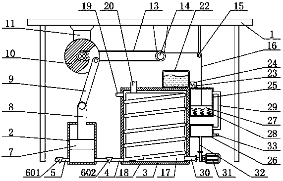
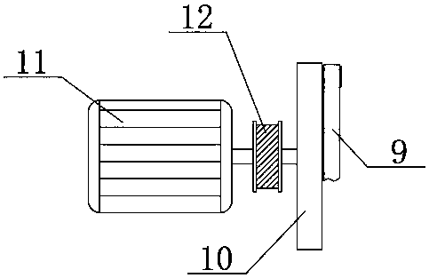
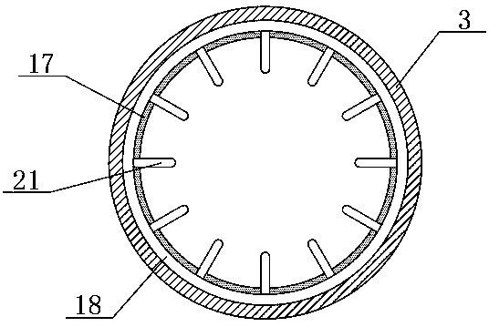
[0021] A metallurgical equipment waste heat recovery device, including a fixed frame 1, a connecting rod 9, a liquid outlet pipe 29 and a belt 13, and the bottom end of the fixed frame 1 is fixedly connected with a motor 11, a second pulley 14 and a pulley in sequence from left to right 15. A cylinder body 2, a heating chamber 3 and a water pump 31 are sequentially arranged under ...


PUM


Abstract

The invention relates to the technical field of waste heat recycling, in particular to a metallurgical equipment waste heat recycling device. The metallurgical equipment waste heat recycling device comprises a fixing bracket, a connecting rod, a liquid outlet pipe and a belt. A cylinder body, a heating bin and a water pump are arranged below the fixing bracket in sequence from left to right. A piston is connected into the cylinder body in a sliding manner. An air inlet pipe is fixedly connected to the left side of the cylinder body. An air guiding pipe is fixedly connected to the right side ofthe cylinder body. The right end of the air guiding pipe is fixedly connected with the heating bin. The heating bin is internally provided with a large water tank. A small water tank is arranged at the right side of the top end of the heating bin. A disinfection tank is fixedly connected to the right side of the heating bin. A water storage tank is arranged below the disinfection tank. A water outlet pipe is fixedly connected to the right side of the large water tank, and the right end of the water outlet pipe is connected with the water pump. A water delivery pipe is fixedly connected to theoutput end of the water pump and the water storage tank. By means of the metallurgical equipment waste heat recycling device, waste heat in a metallurgic plant can be recycled; the utilization rate is high; benefits of the plant are increased; and the metallurgical equipment waste heat recycling device is worthy of being popularized.

Description

technical field [0001] The invention relates to the technical field of waste heat recovery, in particular to a metallurgical equipment waste heat recovery and utilization device. Background technique [0002] Waste heat refers to the usable heat energy released during the production process, mainly including high-temperature waste gas, etc. Waste heat recovery and utilization can generate steam through waste heat boilers, drive steam turbines to do mechanical work or generate electricity, and can also be used for heating or hot water production. Metallurgical plants While consuming energy to promote material transformation, a large amount of waste heat and pressure will be generated. Therefore, the effective recycling of various waste heat and pressure is an important way for the iron and steel industry to save energy and reduce consumption. Therefore, the demand for waste heat recovery and utilization devices is increasing. [0003] However, at present, metallurgical plants...

Claims


Application Information

Patent Timeline
IPC IPC(8): F27D17/00
CPCF27D17/004Y02P10/25
Inventor 李明科
Owner 李明科
Features
  • Generate Ideas
  • Intellectual Property
  • Life Sciences
  • Materials
  • Tech Scout
  • Unparalleled Data Quality
  • Higher Quality Content
  • 60% Fewer Hallucinations
Learn More