Automatic calibration system and method of permanent magnet synchronous motor for electric vehicles

A technology of permanent magnet synchronous motor and automatic calibration system, which is applied in the direction of motor generator test, measurement of electricity, measurement of electric variables, etc., can solve the problems of long calibration period, unsatisfactory accuracy, and long time consumption.

Active Publication Date: 2018-06-29
SHANGHAI DAJUN TECH
View PDF7 Cites 17 Cited by
  • Summary
  • Abstract
  • Description
  • Claims
  • Application Information

AI Technical Summary

Problems solved by technology

[0003] The traditional motor calibration method is to construct a mathematical model of the motor according to the parameters such as the maximum current of the motor controller, the maximum output voltage, and the maximum torque of the motor, and then generate the current command values ​​corresponding to each torque at different speeds according to the mathematical model, and convert these current commands to The values ​​are tabulated and burned into the microprocessor of the motor controller for actual test calibration; since many parameters of the motor itself are unknown, engineers can only set an initial value based on personal experience when constructing the mathematical model of the motor. Then, the calibration is repeated through actual tests, which takes a long time and the accuracy is not satisfactory, which limits the commercialization process and application of a new product of a permanent magnet synchronous motor control system for electric vehicles
[0004] In order to solve the problems of low precision and long calibration cycle of the traditional motor calibration method, the present invention provides a new type of motor automatic calibration system, the automatic calibration bench such as figure 1 shown

Method used


Image

  • Automatic calibration system and method of permanent magnet synchronous motor for electric vehicles

Examples


Embodiment Construction

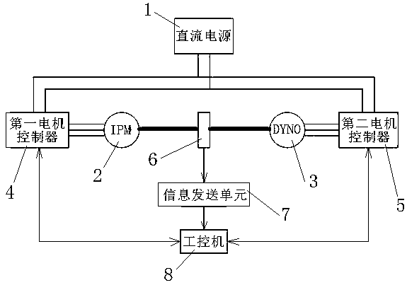
[0029] Example figure 1As shown, the automatic calibration system of the permanent magnet synchronous motor for electric vehicles of the present invention includes a DC power supply 1, a motor under test 2 and a dynamometer 3, the motor under test 2 is connected to the dynamometer with 3 shafts, and the system also includes a first A motor controller 4, a second motor controller 5, a torque speed sensor 6, an information sending unit 7 and an industrial computer 8, the DC power supply 1 is electrically connected to the first motor controller 4 and the second motor controller 5 respectively connected to provide a DC voltage, the first motor controller 4 and the second motor controller 5 are electrically connected to the motor under test 2 and the dynamometer 3 respectively and control the motor under test 2 and the dynamometer 3 to run, so The torque speed sensor 6 is mechanically connected with the motor under test 2 and the dynamometer 3 to collect torque and speed informatio...


PUM


Abstract

The invention discloses an automatic calibration system and method of a permanent magnet synchronous motor for electric vehicles. The system is composed of a measured motor, a dynamometer and corresponding motor controllers. A torque and speed sensor is used for detecting the torques and speeds of the measured motor and the dynamometer and transmitting the torques and speeds to an industrial personal computer through an information sending unit. The industrial personal computer is in communication connection with the corresponding motor controllers. In the method, the industrial personal computer automatically measures all current command values satisfying the limit voltages and currents of the motor controllers, records the stator voltage, magnetic flux, torque, temperature and other parameters under each current command value, and finds out the optical current command value satisfying the motor controllers through interpolating and fitting. As calibration is carried out according toactual measured data, high accuracy is achieved. Moreover, the system and the method run automatically, and have high calibration speed. Therefore, the development of new products is accelerated, andthe research and development costs are reduced.

Description

technical field [0001] The invention relates to an automatic calibration system and method for a permanent magnet synchronous motor used in an electric vehicle. Background technique [0002] Permanent magnet synchronous motors are widely used in the field of new energy electric vehicles due to their advantages such as high power density, high efficiency, and wide speed range. However, to realize these advantages of permanent magnet synchronous motors, they must be precisely controlled. The inner loop of the vehicle permanent magnet synchronous motor control system is the current loop, which receives the torque command from the accelerator pedal or the speed loop, and then parses the torque command into the current command value in the synchronous rotating coordinate system . The analytical principle generally adopted at present is that the stator current value is the smallest at a certain torque at a specific speed. Generally, the current command value corresponding to eac...

Claims


Application Information

Patent Timeline
Patent Type & Authority Applications(China)
IPC IPC(8): G01R31/34
CPCG01R31/343
Inventor 陈双王双全杜朝辉
Owner SHANGHAI DAJUN TECH
Why Eureka
Try Eureka