SAR (Synthetic Aperture Radar) imaging method based on weighted sparsity bayesian recovery via iterative minimum algorithm

A sparse Bayesian and reconstruction algorithm technology, applied in the field of radar and synthetic aperture radar imaging, can solve problems such as difficult to improve, influence, resolution limitation, etc.

Active Publication Date: 2018-06-29
UNIV OF ELECTRONIC SCI & TECH OF CHINA
View PDF3 Cites 12 Cited by
  • Summary
  • Abstract
  • Description
  • Claims
  • Application Information

AI Technical Summary

Problems solved by technology

[0006] The resolution of the traditional SAR imaging method based on matched filtering is limited. Specifically, the resolution in the range direction is affected by the signal bandwidth, the resolution along the track is affected by th

Method used


Image

  • SAR (Synthetic Aperture Radar) imaging method based on weighted sparsity bayesian recovery via iterative minimum algorithm
  • SAR (Synthetic Aperture Radar) imaging method based on weighted sparsity bayesian recovery via iterative minimum algorithm
  • SAR (Synthetic Aperture Radar) imaging method based on weighted sparsity bayesian recovery via iterative minimum algorithm

Examples


Embodiment Construction

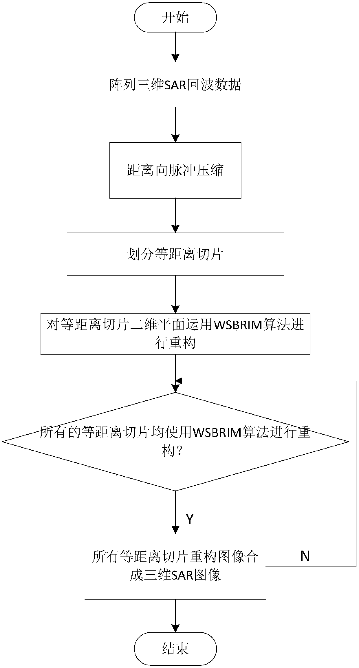
[0080] The present invention mainly adopts the method of computer simulation for verification, and all steps and conclusions are verified correctly on MATLAB-R2014b. The specific implementation steps are as follows:

[0081] Step 1. Initialize SAR system parameters:

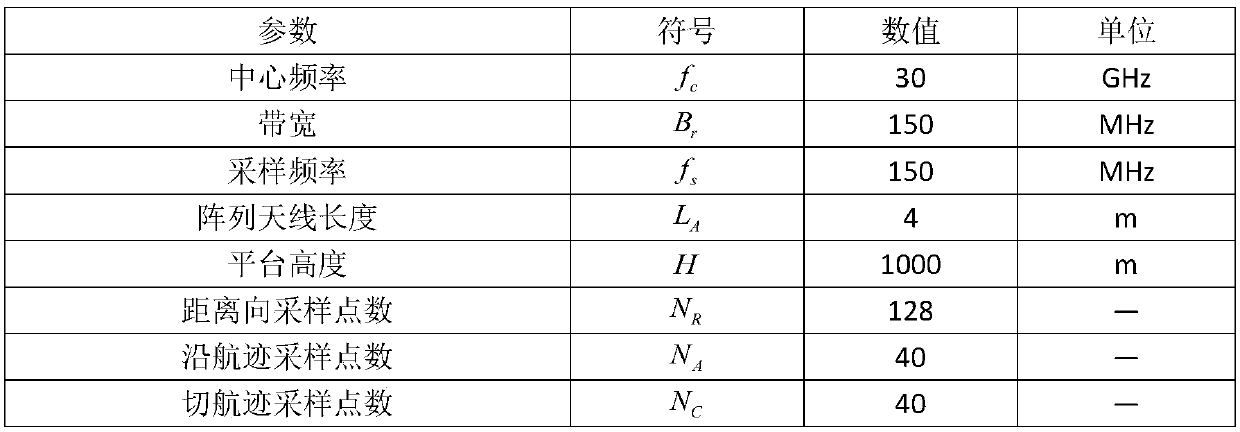
[0082] The initial SAR system parameters include: the platform velocity vector is recorded as The initial position vector of each element of the linear array antenna, denoted as Among them, n is the serial number of each array element of the antenna, which is a natural number, n=1,2,...,N, N=4096 is the total number of array elements of the linear array antenna, and the length of the linear array antenna is recorded as L=3m; Frequency f c =30GHz; the frequency modulation slope f of the radar transmitting signal dr =3×10 14 Hz / s; the pulse repetition time is recorded as PRI=2ms; the pulse repetition frequency of the radar system PRF=500Hz; the bandwidth of the radar emission signal B r =1.5=10 8 Hz, the p...


PUM


Abstract

The invention discloses an SAR (Synthetic Aperture Radar) imaging method based on a weighted sparsity bayesian recovery via iterative minimum (WSBRIM) algorithm. The SAR imaging method is characterized in that a linear measurement matrix of a scattering coefficient in a raw echo signal and observation scene target space of a linear array SAR is established by aiming at the characteristic that a primary scattering object in a linear array SAR observation scene target space is sparse in space. The SAR imaging method comprises the following steps: weighing an L1 norm in a cost function on the basis of an SBRIM algorithm; carrying out pulse compression on distance; dividing equidistant surfaces; then carrying out sparsity reconstruction on each equidistant two-dimensional plane. Compared witha traditional method, the SAR imaging method disclosed by the invention has the characteristics of high reconstruction precision and high operation efficiency, and can be suitable for the fields of SAR imaging, geological remote sensing and the like.

Description


Claims


Application Information

Patent Timeline
Owner UNIV OF ELECTRONIC SCI & TECH OF CHINA
Why Eureka
Try Eureka