
Three-phase high-frequency transformer

A three-phase high-frequency, transformer technology, applied in the direction of fixed transformer or mutual inductance, transformer/inductor core, transformer/inductor components, etc. Large difference in resistance and other problems, to achieve the effect of small occupied space, low manufacturing cost, and balanced magnetoresistance

Pending Publication Date: 2018-06-29
上海意兰可电力电子设备有限公司 +2
View PDF0 Cites 1 Cited by
  • Summary
  • Abstract
  • Description
  • Claims
  • Application Information

AI Technical Summary

Problems solved by technology

If the traditional three-phase transformer core structure is used, the reluctance of the three-phase loops will be quite different, which cannot solve the problem of unbalanced three-phase reluctance.

Method used


Image

  • Three-phase high-frequency transformer
  • Three-phase high-frequency transformer
  • Three-phase high-frequency transformer

Examples


Embodiment Construction

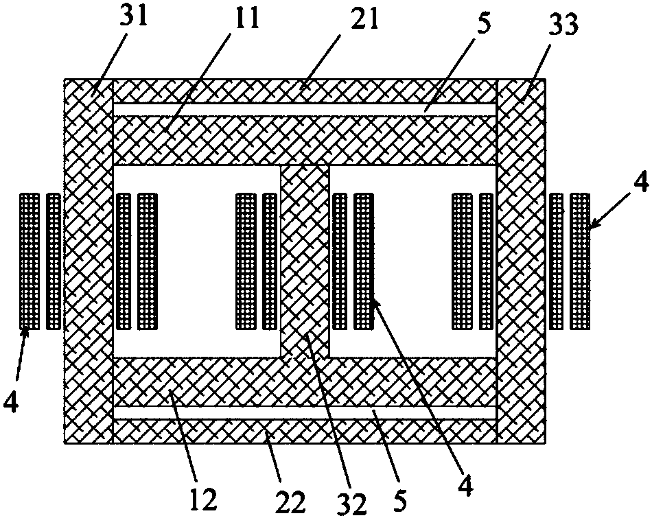
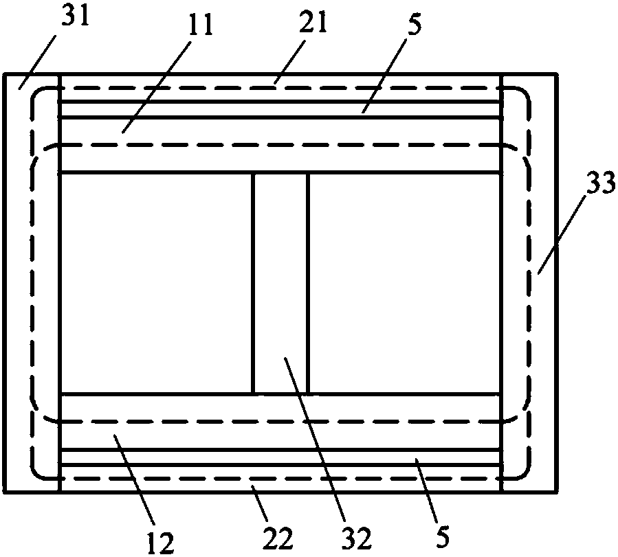
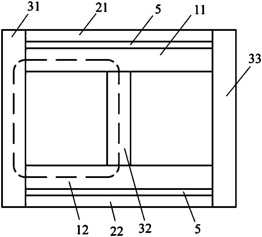
[0022] Such as figure 1 The three-phase high-frequency transformer shown includes: an upper main iron yoke 11, a lower main iron yoke 12, an upper auxiliary iron yoke 21, a lower auxiliary iron yoke 22, an iron core column 31, an iron core column 32, and an iron core column 33 . Among them, the upper main iron yoke 11, the lower main iron yoke 12, the upper auxiliary iron yoke 21, and the lower auxiliary iron yoke 22 are silicon steel yokes, amorphous / nanocrystalline iron yokes or ferrite magnetic powder iron yokes, the iron core column 31, the iron core Column 32 and core column 33 are silicon steel core columns, amorphous / nanocrystalline core columns or ferrite magnetic powder core columns.

[0023] The iron core column 31 and the iron core column 33 are arranged on both sides, and the iron core column 32 is arranged in the middle, and each iron core column is wound with a coil 4, including a primary coil and a secondary coil, and three primary coils on three iron core colu...


PUM


Abstract

The invention relates to a three-phase high-frequency transformer and aims to provide the three-phase high-frequency transformer to realize three-phase magnetic reluctance balance. Ferrite can be usedas magnetic cores of iron core columns, and structural simplicity is realized. The three-phase high-frequency transformer comprises an upper main iron yoke, a lower main iron yoke and three iron corecolumns, and each iron core column is provided with a primary coil and a secondary coil by winding. Two ends of the upper main iron yoke are connected to the two iron core columns on two sides, two ends of the lower main iron yoke are connected to the two iron core columns on two sides, and upper and lower ends of the middle iron core column are connected with the middle of the upper main iron yoke and the middle of the lower main iron yoke respectively. An upper auxiliary iron yoke is arranged above the upper main iron yoke, two ends of the upper auxiliary iron yoke are connected to the twoiron core columns on two sides, and a gap is reserved between the upper auxiliary iron yoke and the upper main iron yoke. A lower auxiliary iron yoke is arranged below the lower main iron yoke, two ends of the lower auxiliary iron yoke are connected to the two iron core columns on two sides, and a gap is reserved between the lower auxiliary iron yoke and the lower main iron yoke.

Description

technical field [0001] The invention relates to power electronic equipment, in particular to a three-phase high-frequency transformer. Background technique [0002] With the development of power electronics technology and the application of high-frequency and high-power power electronic devices, the frequency of power electronic equipment is getting higher and higher, and the capacity is increasing. Therefore, high-frequency and high-power transformers are required to adapt to it. Recently, with the emergence of high-power high-frequency switching devices and magnetic cores, conditions have been created for the manufacture of high-frequency high-power transformers. [0003] In the past, the large-capacity transformer had a working frequency of 50Hz or 60Hz, which was called a power frequency transformer. When the operating frequency of the transformer in the power electronic system is tens or hundreds of kilohertz, it can be called a high-frequency transformer relative to t...

Claims


Application Information

Patent Timeline
IPC IPC(8): H01F27/24H01F27/255H01F19/04
CPCH01F27/24H01F19/04H01F27/255
Inventor 徐启惠曹仲飞曹祥雄
Owner 上海意兰可电力电子设备有限公司
Learn More