Wireless charging device
A wireless charging and coil technology, applied in circuit devices, circuits, inductors, etc., can solve the problem of reducing the charging efficiency of wireless charging coils, achieve good electromagnetic shielding effect, increase magnetic circuit area, and improve efficiency.
- Summary
- Abstract
- Description
- Claims
- Application Information
AI Technical Summary
Problems solved by technology
Method used
Image
Examples
Embodiment 1
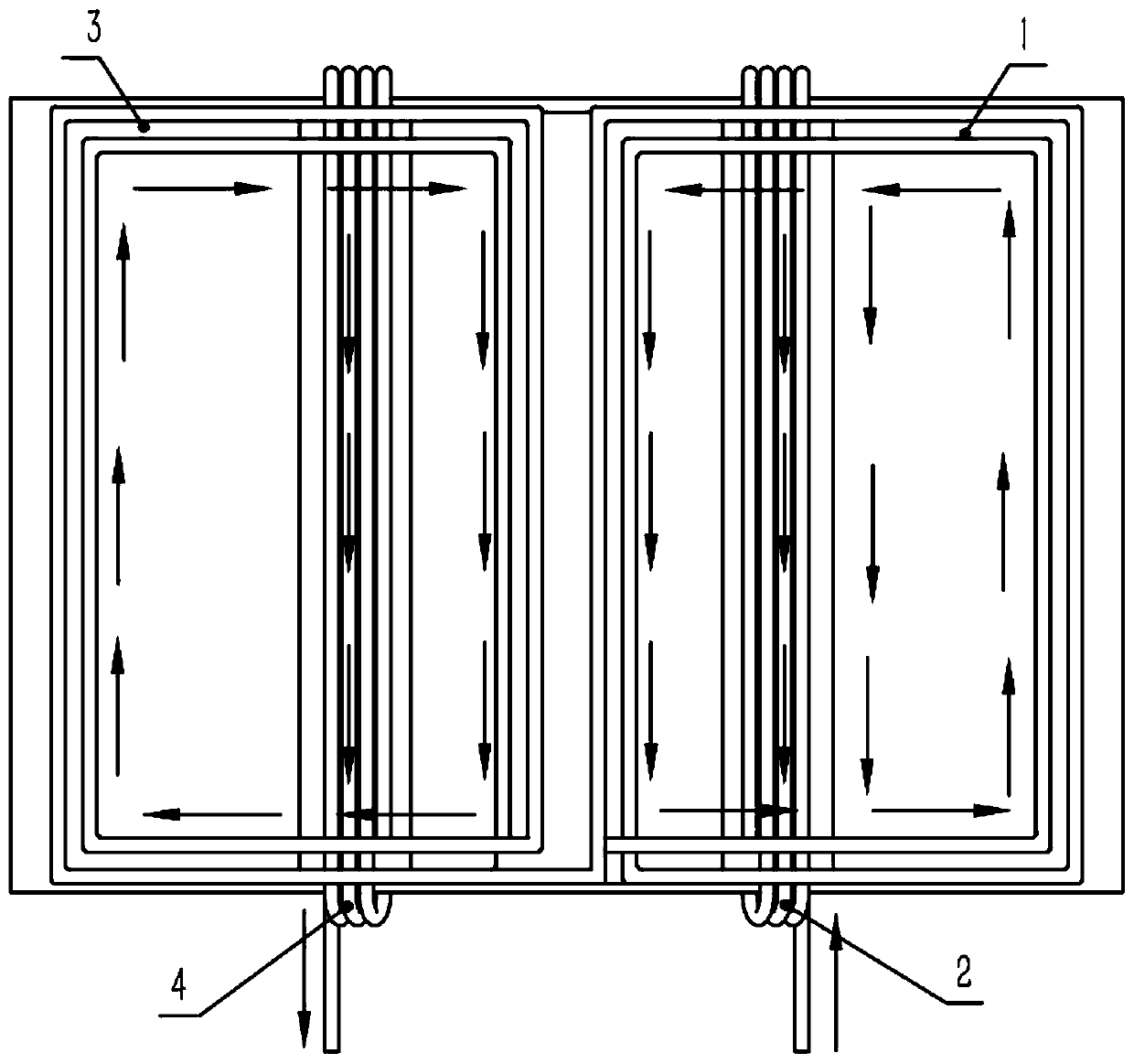
[0033] Such as figure 1 The shown wireless charging device includes a wireless charging coil, electromagnetic shielding plates (8-1, 8-2) and a U-shaped aluminum plate shielding layer 9, wherein the wireless charging coil includes an excitation layer 5, and is wound by the same insulated wire The formed first coil loop loop 1 , the second coil loop loop 2 , the third coil loop loop 3 , and the fourth coil loop loop 4 . In order to describe the positional relationship of the four coil loops, in figure 1 The coordinate system is drawn with the vertical line of the excitation layer as the y-axis and the horizontal direction along the excitation layer as the x-axis.
[0034] Such as figure 1 As shown, the four coil loops are respectively located in four quadrants, and the winding shapes are all rectangular. Wherein, the first coil loop 1 and the third coil loop 3 are adjacently arranged on the upper end surface of the excitation layer 5 , and the planes of the first coil loop 1...
Embodiment 2
[0047] The wireless charging device of this embodiment is as Figure 5 , Figure 6 As shown, it includes a wireless charging coil and an electromagnetic shielding plate 8. The wireless charging coil includes an excitation layer 5 and a coil loop loop wound by the same insulated wire. The coil loop loop includes a first coil loop loop 1 and a second coil loop loop 2, wherein the first coil loop 1 is arranged on the upper end surface of the excitation layer 5 , and the plane where the first coil loop 1 is located is parallel to the excitation layer 5 .
[0048] The second coil loop loop 2 is arranged around the upper and lower end surfaces and two side surfaces of the excitation layer 5; The current direction of 1 is the same, and the edge 2-1 of the second coil annular loop on the upper end face is set close to the edge 1-1 of the first coil annular loop. The upper end surface of the excitation layer 5 is provided with a groove, and when the number of coil turns of the second...
PUM
 Abstract
Description
Claims
Application Information
 - R&D
- Intellectual Property
- Life Sciences
- Materials
- Tech Scout
- Unparalleled Data Quality
- Higher Quality Content
- 60% Fewer Hallucinations
Browse by: Latest US Patents, China's latest patents, Technical Efficacy Thesaurus, Application Domain, Technology Topic, Popular Technical Reports.
© 2025 PatSnap. All rights reserved.Legal|Privacy policy|Modern Slavery Act Transparency Statement|Sitemap|About US| Contact US: help@patsnap.com


