Motor rotating shaft and magnetic levitation motor

A technology of motor shaft and magnetic suspension bearing, which is applied to magnetic circuits, electrical components, electromechanical devices, etc., can solve the problems of increasing the control difficulty of magnetic suspension bearings, reducing the control accuracy of magnetic suspension bearings, and reducing bearing output, so as to reduce the control accuracy and control difficulty. , Improve working performance, improve the effect of bearing output

Pending Publication Date: 2020-04-17
GREE ELECTRIC APPLIANCES INC
View PDF0 Cites 1 Cited by
  • Summary
  • Abstract
  • Description
  • Claims
  • Application Information

AI Technical Summary

Problems solved by technology

[0004] The disadvantage of this kind of three-section shaft design is that the front and rear short shafts can only use non-magnetic materials, because if the magnetic steel rings are made of magnetic materials, the magnetic leakage magnetic circuit will be formed in the axial direction, which will cause the magnetic suspension bearings at both ends of the shaft to rotate. The interference of the magnetic field will increase the difficulty of magnetic suspension bearing control and reduce the control accuracy of magnetic suspension bearings; while the use of non-magnetic materials for the front and rear short shafts will limit the magnetic circuit of magnetic suspension bearings, making it easier for magnetic suspension bearing rotors to reach saturation and reduce bearings. Contribute

Method used


Image

  • Motor rotating shaft and magnetic levitation motor
  • Motor rotating shaft and magnetic levitation motor
  • Motor rotating shaft and magnetic levitation motor

Examples


Embodiment Construction

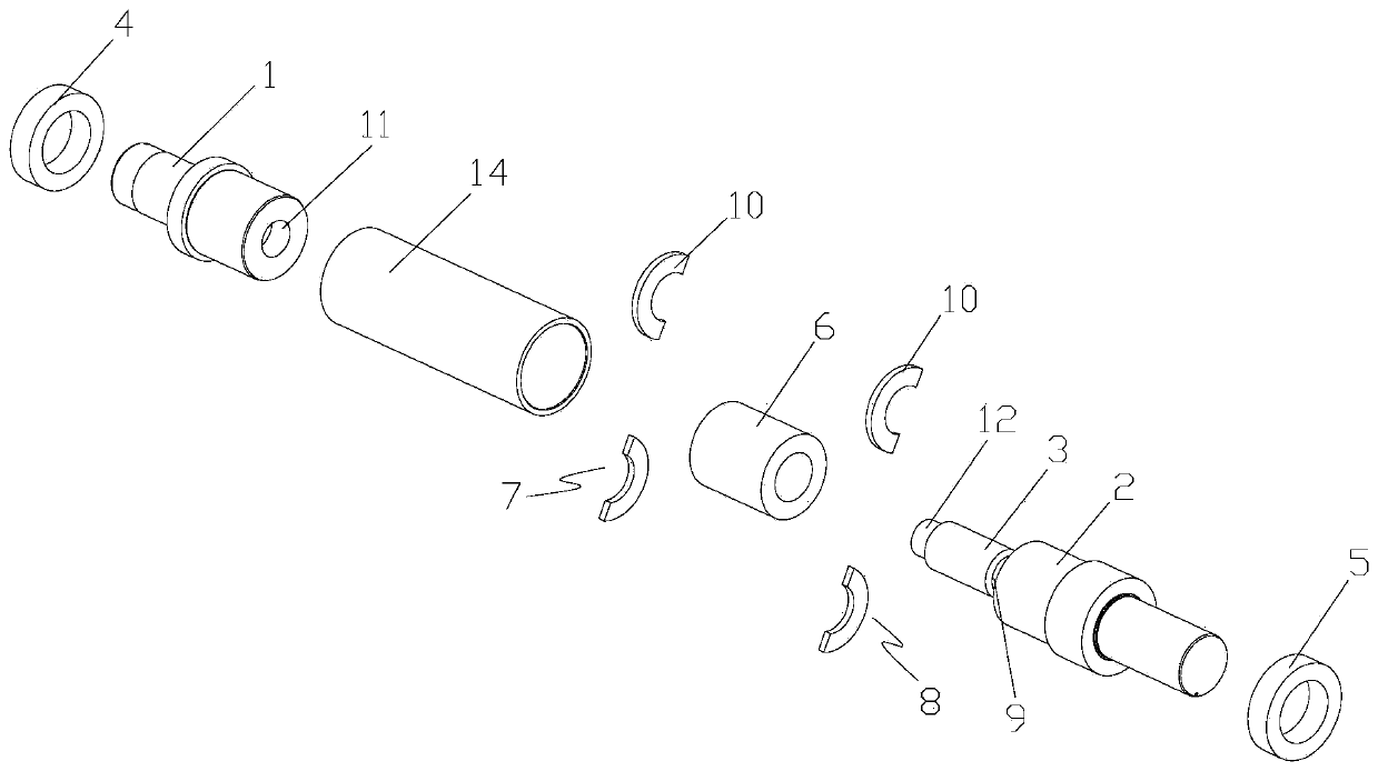
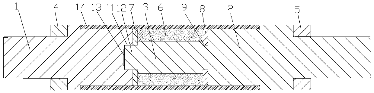
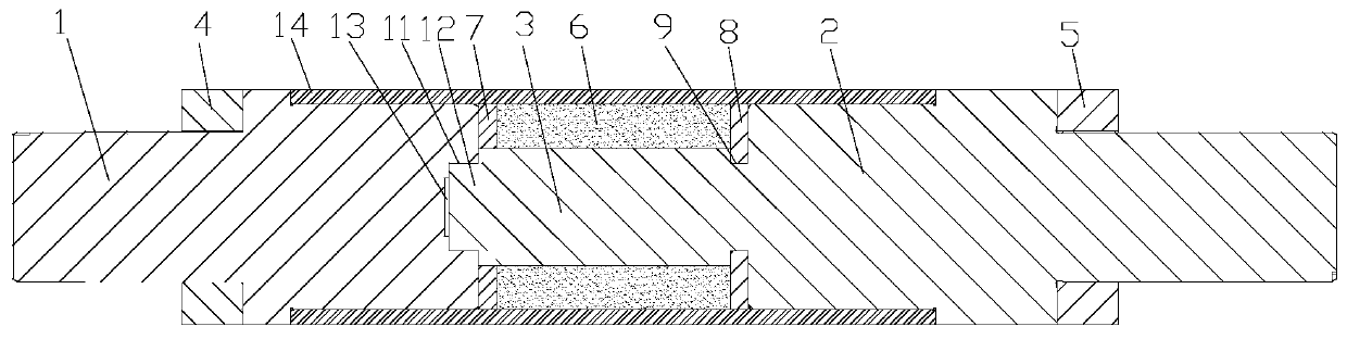
[0026] See also Figure 1 to Figure 4 As shown, according to the embodiment of the present application, the motor shaft includes a front stub shaft 1, a rear stub shaft 2, a core shaft 3, a front magnetic bearing 4, a rear magnetic bearing 5, a magnetic steel ring 6, a first magnetic isolation ring 7 and a first Two magnetic isolation rings 8, the core shaft 3 is set between the front stub shaft 1 and the rear stub shaft 2, the front magnetic suspension bearing 4 is sleeved on the front stub shaft 1, and the rear magnetic suspension bearing 5 is sleeved on the rear stub shaft 2. The steel ring 6 is sleeved outside the mandrel 3, the first magnetic isolation ring 7 and the second magnetic isolation ring 8 are sleeved outside the mandrel 3, and the magnetic steel ring 6 is located on the first magnetic isolation ring 7 and the second magnetic isolation ring 8. In between, the front stub shaft 1 and / or the rear stub shaft 2 are made of magnetically conductive materials. The outer ...


PUM


Abstract

The invention provides a motor rotating shaft and a magnetic levitation motor. The motor rotating shaft comprises a front short shaft, a rear short shaft, a mandrel, a front magnetic suspension bearing, a rear magnetic suspension bearing, a magnetic steel ring, a first magnetic isolation ring and a second magnetic isolation ring, and the mandrel is arranged between the front short shaft and the rear short shaft; the front short shaft is sleeved with the front magnetic suspension bearing; the rear short shaft is sleeved with the rear magnetic suspension bearing; the mandrel is sleeved with themagnetic steel ring; the first magnetic isolation ring and the second magnetic isolation ring sleeve the mandrel, the magnetic steel ring is located between the first magnetic isolation ring and the second magnetic isolation ring, the front short shaft and / or the rear short shaft are / is made of magnetic conductive materials, the outer diameters of the first magnetic isolation ring and the second magnetic isolation ring are the same as the outer diameter of the magnetic steel ring, and the inner diameter of the first magnetic isolation ring and / or the second magnetic steel ring is smaller thanthat of the magnetic steel ring. According to the motor rotating shaft, the output of the magnetic suspension bearing can be increased while the interference of the magnetic field of the magnetic steel ring on the magnetic field of the magnetic suspension bearing is effectively avoided.

Description

Technical field [0001] This application relates to the technical field of motors, and in particular to a motor shaft and a magnetic levitation motor. Background technique [0002] High-speed permanent magnet synchronous motors have many advantages such as high power density, good dynamic response and simple structure, and have become one of the research hotspots in the field of international electrical engineering. However, the permanent magnets in the rotor generally use sintered neodymium iron boron permanent magnet materials. Since this permanent magnet material is resistant to compression and not tensile, in order to ensure that the permanent magnet has sufficient strength at high speeds, the permanent magnet is generally wrapped with a layer The high-strength rotor sheath, the rotor sheath and the permanent magnet adopt an interference fit to ensure that the permanent magnet still bears a certain compressive stress during operation, thereby ensuring the safe operation of the...

Claims


Application Information

Patent Timeline
Patent Type & Authority Applications(China)
IPC IPC(8): H02K7/00H02K5/16H02K1/27
CPCH02K1/2706H02K5/161H02K7/003
Inventor 张小波张芳李广海刘子彬熊博文彭利明梁建东王珊珊张勐胡雄张前亮龚从勇
Owner GREE ELECTRIC APPLIANCES INC
Why Eureka
Try Eureka