Linear Solenoid
A solenoid and linear technology, applied in the field of linear solenoids, can solve the problems of weakening the magnetic attraction force of the plunger and the limitation of the magnetic circuit area of the plunger, and achieve the effect of increasing the magnetic circuit area
- Summary
- Abstract
- Description
- Claims
- Application Information
AI Technical Summary
Problems solved by technology
Method used
Image
Examples
no. 1 example
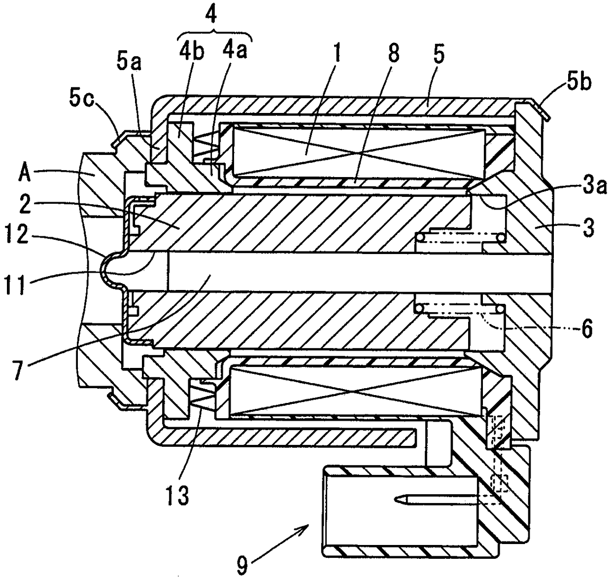
[0015] will refer to figure 1 The first embodiment is described. In the following description, figure 1 The left side in is called left, figure 1 The right side in is called right. In other words, based on figure 1 The left-right direction in the case shown in defines the left-right direction. However, it should be noted that the left-right direction is referred to only for descriptive purposes, and it should not limit the actual direction in the installation situation.
[0016] The linear solenoid of the present embodiment is used, for example, in an electromagnetic hydraulic control valve provided in a hydraulic controller of an automatic transmission. The electromagnetic hydraulic control valve has a hydraulic control valve (such as a spool valve or a ball valve) and a linear solenoid coupled to each other in the axial direction.
[0017] The hydraulic control valve is a normally closed or normally open three-way valve, and has a valve housing A such as a sleeve and a...
no. 2 example
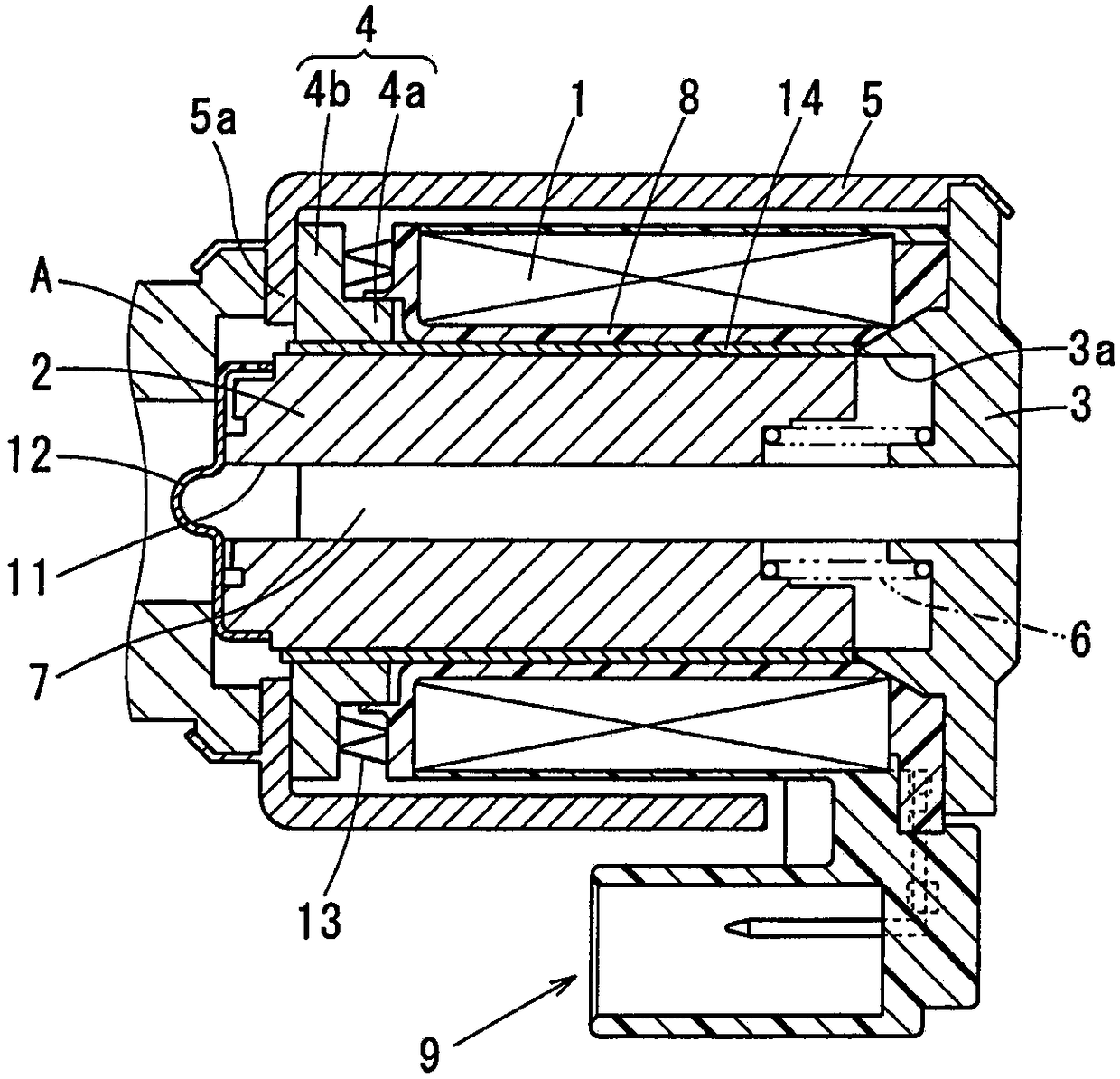
[0053] will refer to figure 2 A second embodiment is described.
[0054] According to a second embodiment, a metal tube 14 that is non-magnetic, in other words made of a non-magnetic metal, is arranged on the inner surface of the coil former 8 in the radial direction, ie the radial inner surface. The inner diameter of the metal tube 14 is slightly larger than the outer diameter of the plunger 2 . Specifically, the metal tube 14 is made of a nonmagnetic metal thin plate (ie, a metal thin plate made of a material such as stainless steel or brass) to have a tube shape. The metal pipe 14 is inserted into the bobbin 8 so as to be located on the inner side of the bobbin 8 in the radial direction.
[0055] When the bobbin 8 expands under the influence of heat or the like, the inner diameter of the bobbin 8 may shrink. By arranging the metal tube 14 having an inner diameter slightly larger than the outer diameter of the plunger 2 on the inner side of the bobbin 8, the inner diamet...
no. 3 example
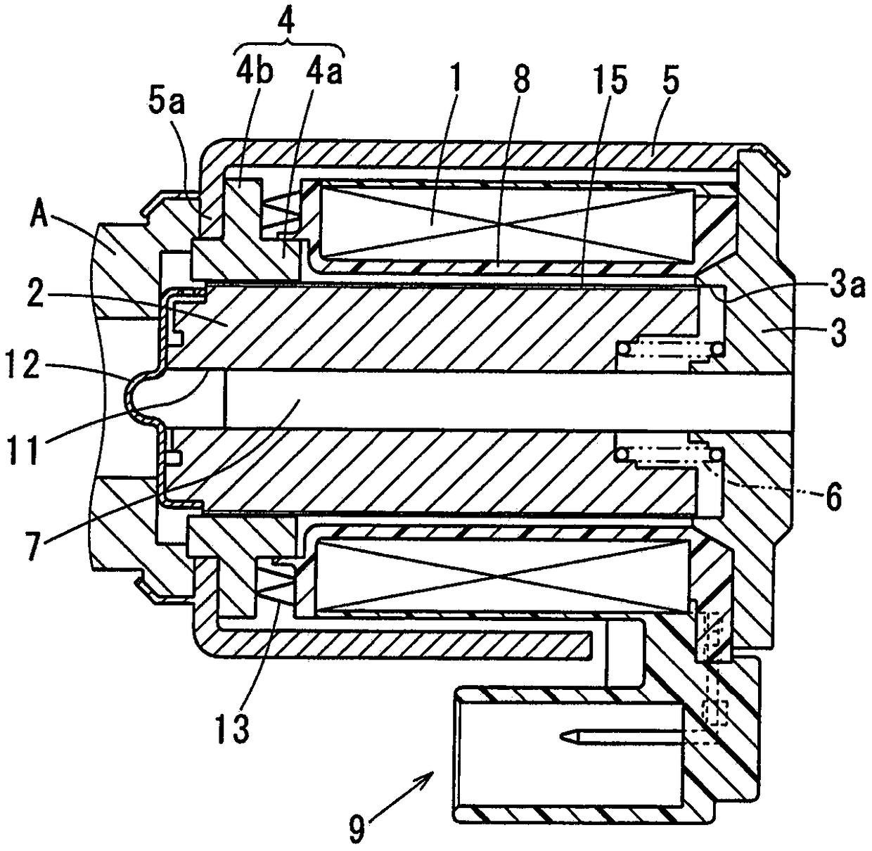
[0062] will refer to image 3 A third embodiment is described.
[0063] According to a third embodiment, a non-magnetic membrane part 15 , in other words made of a non-magnetic material, is arranged on the radially outer surface of the plunger 2 .
[0064] The membrane member 15 is provided (ie adhered) on the radially outer surface of the plunger 2 by a method such as plating or coating. The film member 15 may be made of a resin material such as Teflon (trademark) or a metal material such as copper or nickel.
[0065] According to the third embodiment, with the non-magnetic film member 15 disposed on the radially outer surface of the plunger 2, the same effects as those of the second embodiment can be obtained.
PUM
 Abstract
Description
Claims
Application Information
 - R&D
- Intellectual Property
- Life Sciences
- Materials
- Tech Scout
- Unparalleled Data Quality
- Higher Quality Content
- 60% Fewer Hallucinations
Browse by: Latest US Patents, China's latest patents, Technical Efficacy Thesaurus, Application Domain, Technology Topic, Popular Technical Reports.
© 2025 PatSnap. All rights reserved.Legal|Privacy policy|Modern Slavery Act Transparency Statement|Sitemap|About US| Contact US: help@patsnap.com


