Shock absorption and heat dissipation type power distribution cabinet

A power distribution cabinet and heat dissipation technology, which is applied in the substation/power distribution device shell, seismic equipment, electrical components, etc., can solve the problem of poor heat dissipation effect of power distribution cabinet, heat can not be discharged in time, and no shock absorption of power distribution cabinet. and other problems, to achieve the effect of compact structure, strong practicability and stable rotation

Inactive Publication Date: 2018-06-29
罗新华
View PDF6 Cites 10 Cited by
  • Summary
  • Abstract
  • Description
  • Claims
  • Application Information

AI Technical Summary

Problems solved by technology

[0005] Aiming at the deficiencies of the prior art, the present invention provides a shock-absorbing and heat-dissipating power distribution cabinet, which solves the problem that a large amount of heat will be generated during the use of the power distribution cabinet, and most of the power distribution cabinets have poor heat dissipation, so that the The heat cannot be discharged from the power distribution cabinet in time, which will cause the wires in the power distribution cabinet to ignite spontaneously, thus affecting people's electricity consumption, and because most of the power distribution cabinets do not have the function of shock absorption, when the power distribution cabinet is working The power distribution cabinet vibrates and produces noise, which affects people's lives. Therefore, there is an urgent need for a power distribution cabinet with shock absorption and heat dissipation functions.

Method used


Image

  • Shock absorption and heat dissipation type power distribution cabinet
  • Shock absorption and heat dissipation type power distribution cabinet

Examples


Embodiment Construction

[0025] The following will clearly and completely describe the technical solutions in the embodiments of the present invention with reference to the accompanying drawings in the embodiments of the present invention. Obviously, the described embodiments are only some, not all, embodiments of the present invention. Based on the embodiments of the present invention, all other embodiments obtained by persons of ordinary skill in the art without making creative efforts belong to the protection scope of the present invention.

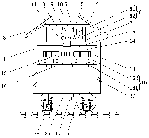
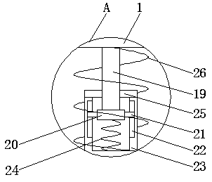
[0026] Such as Figure 1-2 As shown, the present invention provides a technical solution: a shock-absorbing and heat-dissipating power distribution cabinet, including a power distribution cabinet body 1, the upper surface of the power distribution cabinet body 1 is fixedly connected to the bottom end of the support rod 2, and the support rod 2 The top is fixedly connected with the lower surface of the connecting plate 3, the number of supporting rods 2 is four...


PUM


Abstract

The invention discloses a shock absorption and heat dissipation type power distribution cabinet which comprises a power distribution cabinet body, the upper surface of the power distribution cabinet body is fixedly connected with the bottom end of a supporting rod, the top end of the supporting rod is fixedly connected with the lower surface of a connecting plate, solar cell panels are fixedly connected with the left side surface and the right side surface of the connecting plate, the lower surface of the connecting plate is fixedly connected with the top ends of two fixed rods, the opposite surfaces of the two fixed rods are respectively and fixedly connected with the left side surface and the right side surface of a drive device, the outer surface of the drive device is in transmission connection with the outer surface of a driven wheel through a belt, and a first rotating shaft is clamped on the inner surface of the driven wheel. The shock absorption and heat dissipation type powerdistribution cabinet disclosed by the invention achieves the functions of shock absorption and heat dissipation through cooperation among a motor, a drive wheel, the belt, the driven wheel, the firstrotating shaft, a first gear, a second gear, a second rotating shaft, a fan blade, a sliding rod, a sliding groove, a sliding block, a first spring and a shell, thereby facilitating people's work.

Description

technical field [0001] The invention relates to the technical field of power distribution cabinets, in particular to a shock-absorbing and heat-dissipating power distribution cabinet. Background technique [0002] Power distribution cabinets (boxes) are divided into power distribution cabinets (boxes), lighting distribution cabinets (boxes) and metering cabinets (boxes), and are the final equipment of the power distribution system. The power distribution cabinet is a general term for the motor control center. The power distribution cabinet is used in the occasions where the load is relatively dispersed and there are few circuits; the motor control center is used in the occasions where the load is concentrated and there are many circuits. They distribute the electric energy of a certain circuit of the upper-level power distribution equipment to the nearest load. This level of equipment shall provide protection, monitoring and control of the load. [0003] The power distrib...

Claims


Application Information

Patent Timeline
Patent Type & Authority Applications(China)
IPC IPC(8): H02B1/56H02B1/54H02B1/30
CPCH02B1/565H02B1/30H02B1/54
Inventor 罗新华
Owner 罗新华
Why Eureka
Try Eureka