Improved voltage comparator

A technology of voltage comparator and sampling voltage, applied in electrical components, multiple input and output pulse circuits, pulse processing, etc., can solve problems such as process deviation and current mirror mismatch, improve precision, reduce mismatch, The effect of improving the copying accuracy

Active Publication Date: 2018-06-29
WUXI ZGMICRO ELECTRONICS CO LTD
View PDF9 Cites 4 Cited by
  • Summary
  • Abstract
  • Description
  • Claims
  • Application Information

AI Technical Summary

Problems solved by technology

However, due to the process deviation, the output current will not be

Method used


Image

  • Improved voltage comparator
  • Improved voltage comparator
  • Improved voltage comparator

Examples


Example Embodiment

[0023] In order to make the above objectives, features and advantages of the present invention more obvious and understandable, the present invention will be further described in detail below with reference to the accompanying drawings and specific embodiments.

[0024] The "one embodiment" or "embodiment" referred to herein refers to a specific feature, structure, or characteristic that can be included in at least one implementation of the present invention. The appearances of "in one embodiment" in different places in this specification do not all refer to the same embodiment, nor are they separate or selectively mutually exclusive embodiments with other embodiments. Unless otherwise specified, the words connected, connected, and connected in this text indicating electrical connection all mean direct or indirect electrical connection.

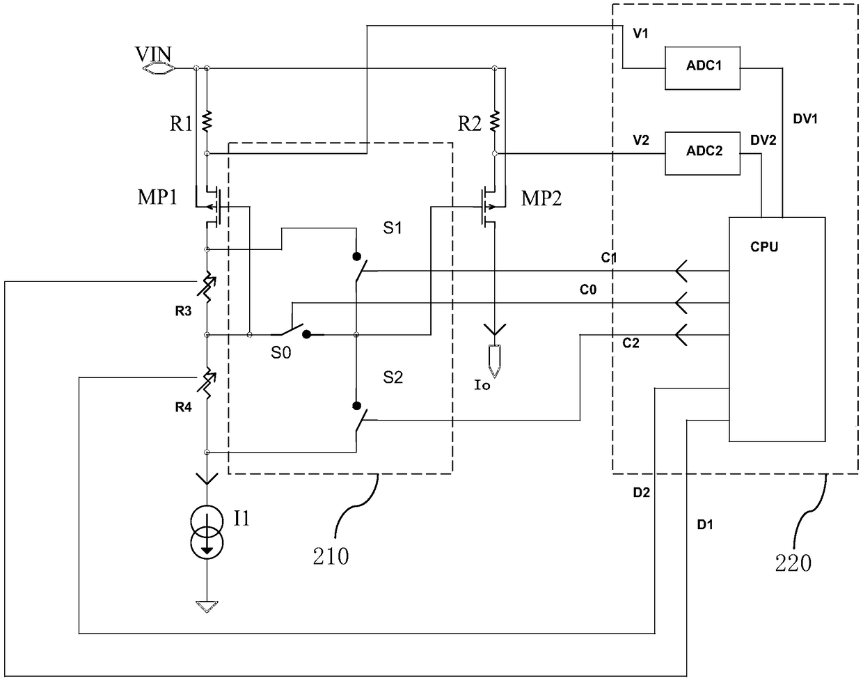
[0025] Please refer to figure 2 As shown, it is a circuit diagram of an improved current mirror circuit in an embodiment of the present inventio...


PUM


Abstract

The invention provides a voltage comparator. The voltage comparator comprises a current mirror circuit, a third resistor, a fourth resistor, a first bipolar transistor, a second bipolar transistor, asecond current source and a third MOS (Metal Oxide Semiconductor) transistor. The current mirror circuit has very small current mirror current duplication mismatch, and very high current duplication precision, so that the precision of an internal reference voltage threshold of the voltage comparator can be increased.

Description

【Technical field】 [0001] The invention relates to the technical field of electronic circuits, in particular to an improved voltage comparator. 【Background technique】 [0002] Current mirrors are widely used in various analog circuits, for example, to generate current bias or as a load for operational amplifiers. However, due to process deviations, the output current is not equal to the input current, which is manifested as a mismatch of the current mirror. [0003] Please refer to figure 1 As shown, it is a schematic circuit diagram of a current mirror in the prior art, which includes PMOS (positive channel Metal Oxide Semiconductor) transistors MP1 and MP2, and the input current source I1 can generate an output current Io through the current mirror. Due to process deviation, there is a mismatch between PMOS transistors MP1 and MP2 during mass production, so that the current value of the output current Io of some chips is greater than the current value of the input current...

Claims


Application Information

Patent Timeline
IPC IPC(8): H03K5/24
CPCH03K5/2481
Inventor 王钊
Owner WUXI ZGMICRO ELECTRONICS CO LTD
Why Eureka
Try Eureka