
Circuit board drilling equipment

A technology for drilling equipment and circuit boards, which is applied in the direction of drilling/drilling equipment, boring/drilling, metal processing equipment, etc. It can solve the problems of no dust removal equipment, heavy workload, long production line, etc., to reduce production cost, increase production efficiency, and improve work efficiency

Inactive Publication Date: 2018-07-03
惠州市源名浩科技有限公司
View PDF0 Cites 5 Cited by
  • Summary
  • Abstract
  • Description
  • Claims
  • Application Information

AI Technical Summary

Problems solved by technology

[0002] During the production process of the circuit board, it is necessary to drill the circuit board. The function of drilling is to prepare for the subsequent processing. The current drilling equipment generally can only drill one type of hole with one drilling machine, and the circuit board needs Drilling many different types of holes requires many different types of drilling machines and many motors, and each drilling needs to be repositioned, the workload is large, the production line is long, the production cost is high, and the drilling efficiency is low, which affects the production efficiency , and there is no dust removal equipment when drilling, which causes debris and powder to fly randomly, which affects the health of the staff. For this reason, we propose a circuit board drilling equipment

Method used


Image

  • Circuit board drilling equipment
  • Circuit board drilling equipment
  • Circuit board drilling equipment

Examples


Embodiment Construction

[0014] The following will clearly and completely describe the technical solutions in the embodiments of the present invention with reference to the accompanying drawings in the embodiments of the present invention. Obviously, the described embodiments are only some, not all, embodiments of the present invention. Based on the embodiments of the present invention, all other embodiments obtained by persons of ordinary skill in the art without making creative efforts belong to the protection scope of the present invention.

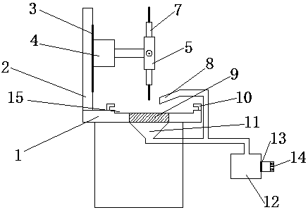
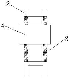
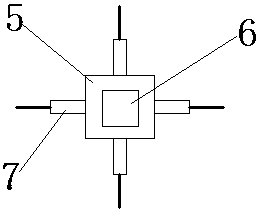
[0015] The present invention provides such Figure 1-3 A kind of circuit board drilling equipment shown comprises drilling table 1, motor 4, rotating block 5 and chip box 12, and the surface of described drilling table 1 is fixed with frame 2, and the surface of described frame 2 A guide rail 3 is provided, a protective case is provided on the outside of the motor 4, the motor 4 is slidingly connected with the guide rail 3 through the protective case, the outp...


PUM

PropertyMeasurementUnit
heightaaaaaaaaaa

Abstract

The invention discloses circuit board drilling equipment comprising a drilling table, a motor, a rotating block and a chip box. A rack is fixed to the surface of the drilling table, and a guide rail is arranged on the surface of the rack; a protecting shell is arranged on the outer side of the motor, the motor is slidably connected with the guide rail through the protecting shell, and an output shaft of the motor is fixedly connected with a rotating block internally provided with a high-speed motor; drilling machines are fixed to the periphery of the rotating block, and an output shaft of thehigh-speed motor is in transmission connection with the drilling machines; a groove is formed in the position, below the rotating block, of the drilling table, and fixing blocks are arranged on the two sides of the groove; a strip-shaped dust suction opening is formed above the fixing blocks and communicates with the chip box through a pipeline; a screen net is arranged on the lower portion of thegroove, a conical dust suction opening is formed in the lower portion of the screen net and communicates with the chip box through a pipeline; and a fan is arranged on the right side of the chip box.The drilling efficiency is high, and the production efficiency is improved.

Description

technical field [0001] The invention belongs to the technical field of circuit board processing, and in particular relates to a circuit board drilling device. Background technique [0002] During the production process of the circuit board, it is necessary to drill the circuit board. The function of drilling is to prepare for the subsequent processing. The current drilling equipment generally can only drill one type of hole with one drilling machine, and the circuit board needs Drilling many different types of holes requires many different types of drilling machines and many motors, and each drilling needs to be repositioned, the workload is large, the production line is long, the production cost is high, and the drilling efficiency is low, which affects the production efficiency , and there is no dust removal equipment when drilling, which causes debris and powder to fly randomly, which affects the health of the staff. For this reason, we propose a circuit board drilling eq...

Claims


Application Information

Patent Timeline
Patent Type & Authority Applications(China)
IPC IPC(8): B23B39/16B23Q11/00
CPCB23B39/16B23Q11/0046
Inventor 陈文雄
Owner 惠州市源名浩科技有限公司
Learn More