Robot spot welding tool and method for antenna array

An antenna element and robot technology, which is applied to welding equipment, auxiliary devices, manufacturing tools, etc., can solve the problems of poor welding consistency, low welding efficiency, and low yield of antenna elements, so as to improve welding quality and efficiency and improve welding efficiency. , the effect of improving consistency

Inactive Publication Date: 2018-07-03
CHINA ELECTRONIC TECH GRP CORP NO 38 RES INST
View PDF14 Cites 2 Cited by
  • Summary
  • Abstract
  • Description
  • Claims
  • Application Information

AI Technical Summary

Problems solved by technology

[0004] The technical problem to be solved by the present invention is that the antenna element welded by manual welding has poor welding consistency, low yield, large deformation and low welding efficiency

Method used


Image

  • Robot spot welding tool and method for antenna array
  • Robot spot welding tool and method for antenna array
  • Robot spot welding tool and method for antenna array

Examples


Embodiment 1

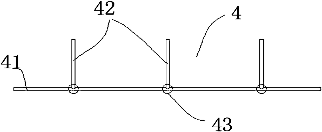
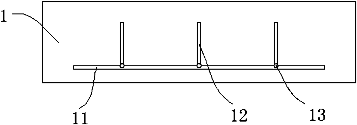
[0034] combined with figure 1 with figure 2 , a robot spot welding tool for an antenna element in the present invention, including a bottom plate 1 for limiting the antenna element, the bottom plate 1 is provided with a long circular groove 11 and a plurality of short circular grooves 12, and the long circular groove 11 is used to place the length of the antenna element 4 The rod 41 and the short circular groove 12 are used to place the short rod 42 of the antenna array 4, the positions of the long circular groove 11 and several short circular grooves 12 correspond to the positions of the long rod 41 and the short rod 42 in the antenna array 4, and the short circular groove 12 One end communicates with the oblong groove 11.

Embodiment 2

[0036] combined with figure 2 , a robot spot welding tool for an antenna array in the present invention, the difference from Embodiment 1 is that the connection between the short circular groove 12 and the long circular groove 11 is provided with a circular groove 13, that is, the short rod 42 and the long rod 41 are embedded respectively The corresponding welding place behind the short round groove 12 and the long round groove 11 is aimed at after the long rod and the short rod are welded on one side, and the welding spot in the welding area after turning over does not hinder the welding accuracy after turning over.

Embodiment 3

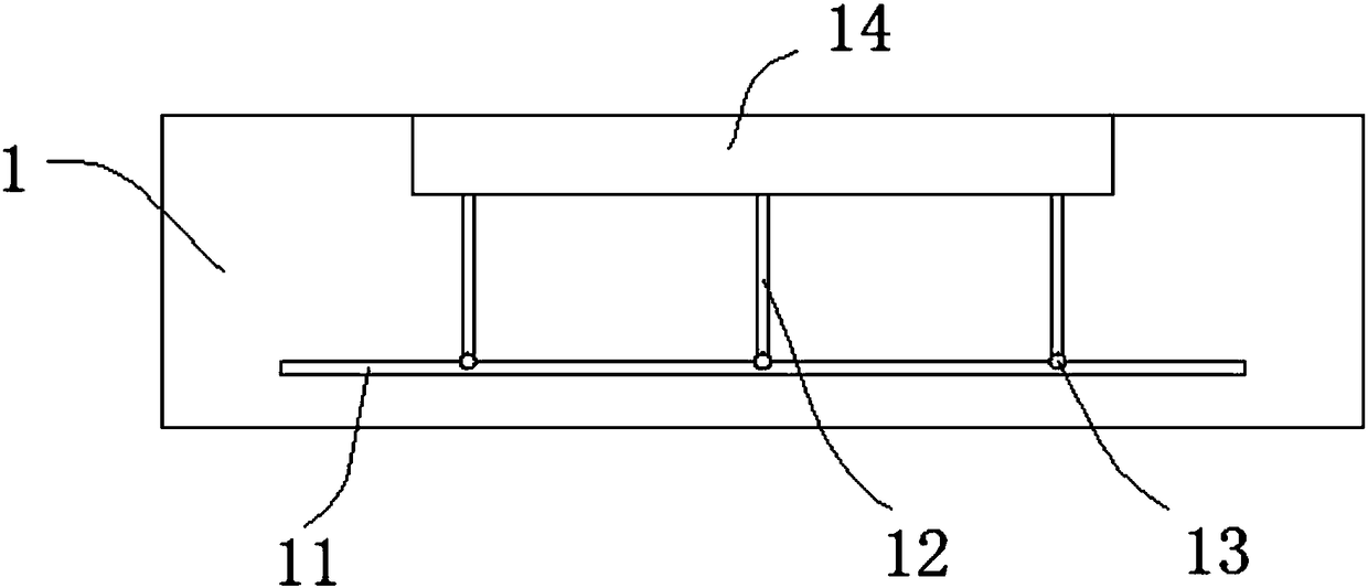
[0038] combined with image 3 with Figure 4 , the robot spot welding frock of a kind of antenna element of the present invention, the difference with embodiment 2 is, also comprises top plate 2, is also provided with side groove 14 on bottom plate 1, one side of side groove 14 and the other side of short circular groove 12 One end is connected, the long rod 41 is placed in the long circular groove 11, the short rod 42 is placed in the short circular groove 12, and the top plate 2 is installed in the side groove 14. Specifically, the top plate 2 is embedded in the side groove 14, and the bottom of the top plate 2 Press the welding point of the short rod 42 and the long rod 41 tightly.


PUM


Abstract

The invention provides a robot spot welding tool and method for an antenna array, and relates to the field of welding tools. The robot spot welding tool for the antenna array comprises a bottom boardprovided with a long round groove and a plurality of short round grooves; a long rod and short rods of the antenna array are arranged on the long round groove and the short round grooves; the long round groove and the short round grooves correspond to the long rod and the short rods in the antenna array in position; and one ends of the short round grooves communicate with the long round groove. The welding uniformity of the long rod and the short rods of the antenna array can be greatly improved, and the welding efficiency and quality are improved.

Description

technical field [0001] The invention relates to the field of welding tooling, in particular to a robot spot welding tooling and method for antenna elements. Background technique [0002] The antenna element is one of the core structures of phased array radar. In low-frequency radar, the commonly used antenna element is a T-shaped antenna, which is made of aluminum alloy rods. In order to improve the radar detection range and accuracy, the array of military radar antennas is getting larger and larger, and the corresponding number of antenna arrays is also very large. [0003] The T-shaped antenna is easy to manufacture due to its simple structure, such as figure 1 It is a structural schematic diagram of the antenna element 4, including a long rod 41 and a short rod 42. The joint between the long rod and the short rod is the welding area 43, which is commonly used for manual argon arc welding. Due to many problems of manual welding, the welding consistency of the antenna elem...

Claims


Application Information

Patent Timeline
Patent Type & Authority Applications(China)
IPC IPC(8): B23K9/007B23K9/167B23K9/235B23K9/32B23K37/04
CPCB23K9/0026B23K9/007B23K9/167B23K9/235B23K9/32B23K37/0443
Inventor 方坤雷伟宋奎晶栾兆菊周继张群梁宁
Owner CHINA ELECTRONIC TECH GRP CORP NO 38 RES INST
Why Eureka
Try Eureka