Compact air-cooled unit

A compact, air-cooled technology, applied in the direction of electromechanical devices, electric components, cooling/ventilation devices, etc., can solve the problems of exhaust fan volume, small power, poor heat dissipation effect of the chassis, damage to generators and power devices, etc., to achieve reduction The overall volume and quality, the effect of improving heat dissipation and improving service life

Pending Publication Date: 2018-07-03
WERNERFUJIAN POWER CO LTD
View PDF0 Cites 3 Cited by
  • Summary
  • Abstract
  • Description
  • Claims
  • Application Information

AI Technical Summary

Problems solved by technology

[0002] Existing generating sets, in order to realize heat dissipation in the case, exhaust fans are often installed on both side walls of the case, because the exhaust fan is set independently of the generator and power unit, when the generator set is working, the exhaust fan will be damaged and the generator and power unit will be damaged. In the case of normal operation, the heat dissipation effect in the chassis cannot be guaranteed at this time. In addition, due to the limited installation space, the volume and power of the exhaust fan are generally small, and the heat dissipation effect in the chassis is poor, which will easily lead to damage to the generator and power unit.
In order to solve the above problems, it is proposed to fix the chassis cooling fan on the generator shaft outside the generator and inside the chassis. The chassis cooling fan is directly driven by the generator and the power unit indirectly, although this can ensure uninterrupted operation of the power unit and generator. Heat dissipation, and compared with the small exhaust fan installed on the side wall of the traditional chassis, the chassis cooling fan indirectly driven by the power unit has higher power and better heat dissipation effect, but it requires the generator shaft to be extended outside the generator, and the chassis needs to be The cooling fan is installed in the chassis, which greatly increases the volume and quality of the generator set on the basis of the current generator set, which in turn limits the application of the generator set in places with small volume and quality requirements

Method used


Image

  • Compact air-cooled unit
  • Compact air-cooled unit
  • Compact air-cooled unit

Examples


Embodiment Construction

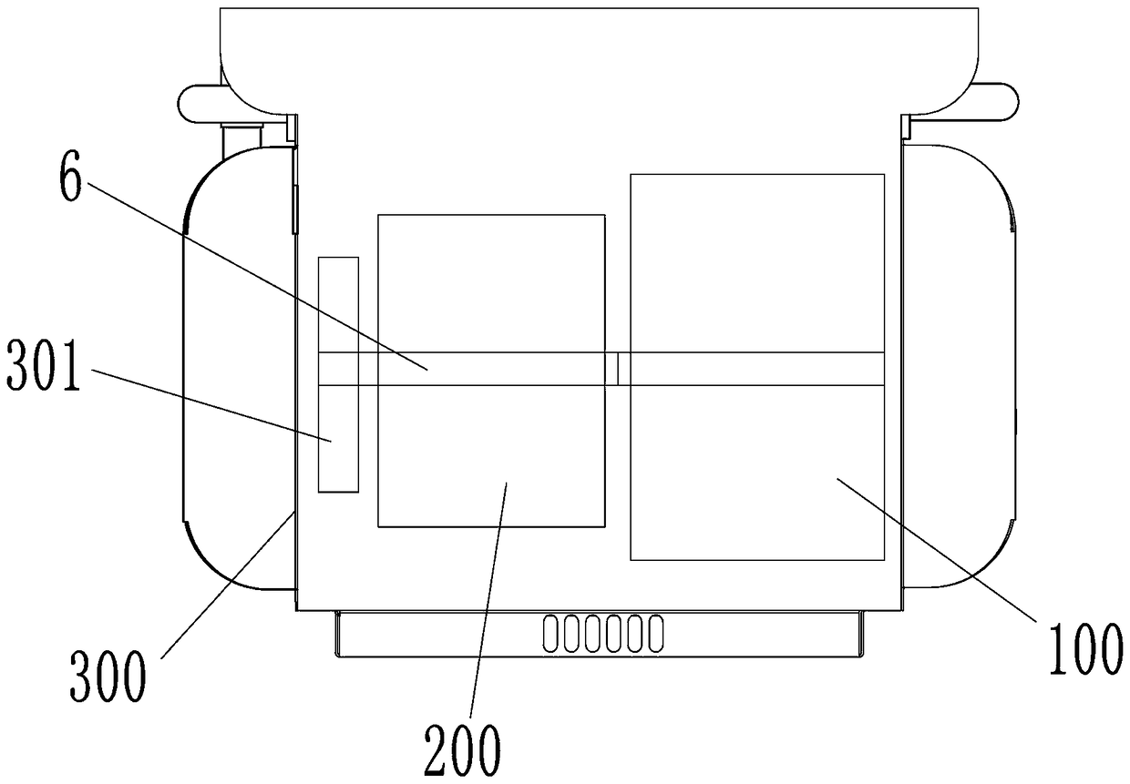
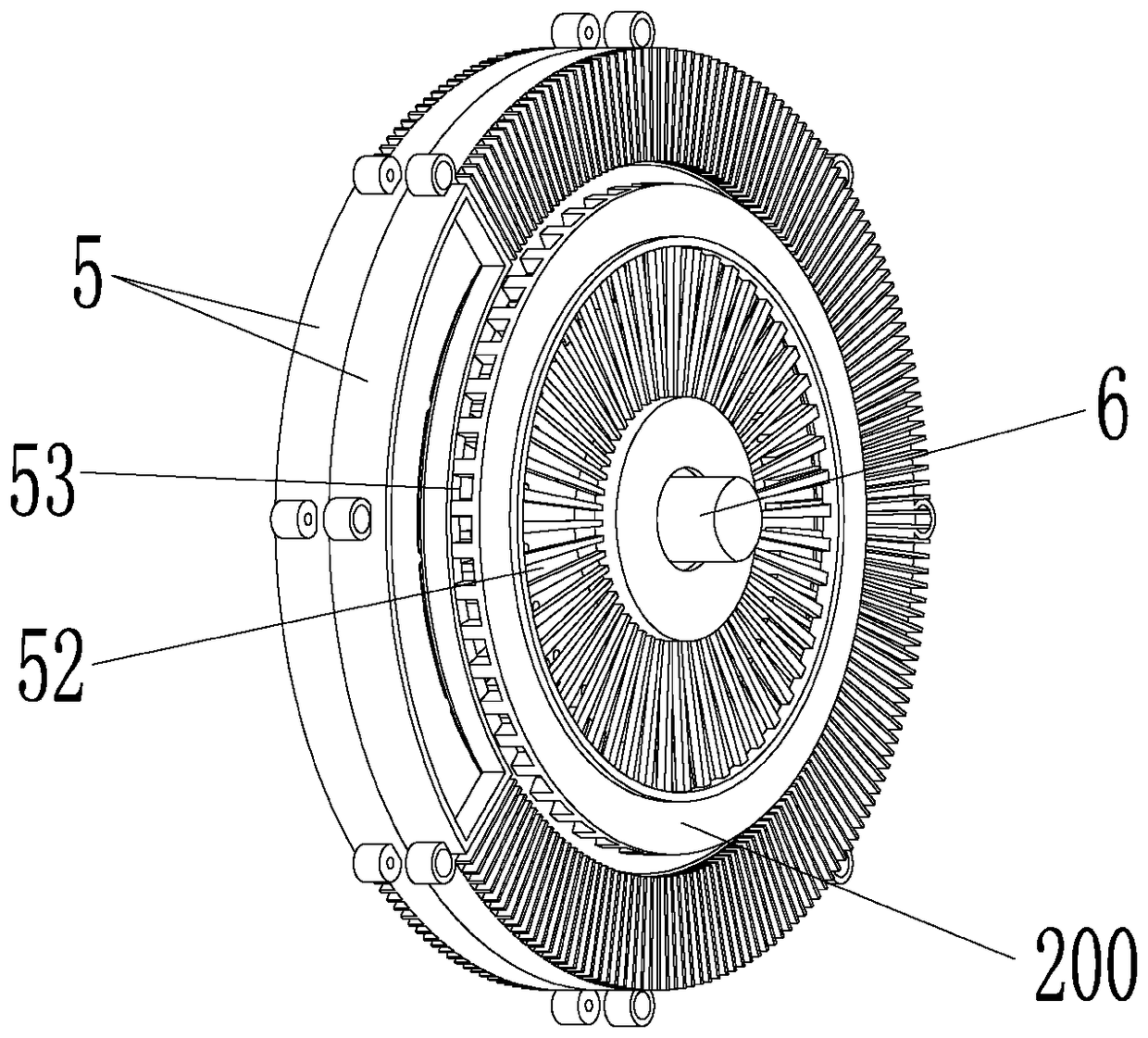
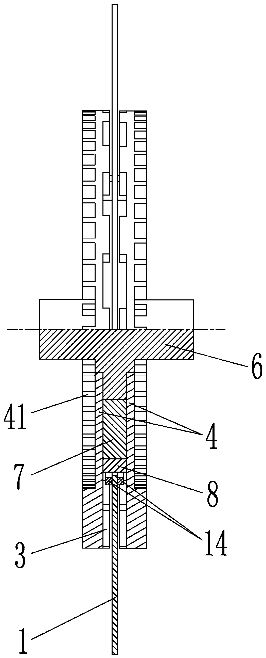
[0024] Figure 1 to Figure 9 The first embodiment of the light-weight and compact electromechanical integrated machine of the present invention is shown. Such as Figure 1 to Figure 4 As shown, the compact air-cooled unit of the present invention includes a chassis 300, a power unit 100 and a generator 200 that are adjacently connected coaxially in the chassis 300, and the end of the generator motor shaft 6 away from the power unit 100 extends to the generator 200 but does not go out of the chassis 300, extending to the outer motor shaft extension of the generator 200 and fixing a chassis cooling fan 301, the generator 200 includes a PCB stator 1 coaxially arranged with the motor shaft 6, and an electronic module 2 The two sides of the PCB stator 1 are symmetrical and outwardly provided with a magnetic steel rotor 3, a heat dissipation shell 4 and an end cover 5 respectively, the heat dissipation shell 4 is sleeved on the motor shaft 6, and the end cover 5 is rotatable. Slee...


PUM


Abstract

The invention discloses a compact air-cooled unit, which comprises a cabinet, a power device and a generator, wherein the power device and the generator are arranged in the cabinet and are adjacentlyand coaxially connected; one end, far away from the power device, of the generator motor shaft extends out of the generator but does not pass through the cabinet; a cabinet cooling fan is fixed on a motor shaft extending section extending out of the generator; and the generator comprises a PCB stator coaxially arranged with the motor shaft and an electronic module. According to the compact air-cooled unit disclosed in the invention, the PCB generator with a small size and a small mass is adopted, the generator unit with the same size thus internally has the space for enabling the motor shaft to extend out of the generator, mounting of the cabinet cooling fan is thus facilitated, on the basis of the existing generator set, the whole size of the generator set does not need to be increased, the cabinet cooling fan can be mounted on the generator motor shaft, and the cooling effects in the cabinet are improved.

Description

technical field [0001] The invention relates to a motor, in particular to a compact air-cooled unit. Background technique [0002] Existing generating sets, in order to realize heat dissipation in the case, exhaust fans are often installed on both side walls of the case, because the exhaust fan is set independently of the generator and power unit, when the generator set is working, the exhaust fan will be damaged and the generator and power unit will be damaged. In the case of normal operation, the heat dissipation effect in the chassis cannot be guaranteed at this time. In addition, due to the limited installation space, the volume and power of the exhaust fan are generally small, and the heat dissipation effect in the chassis is poor, which will easily lead to damage to the generator and power unit. . In order to solve the above problems, it is proposed to fix the chassis cooling fan on the generator shaft outside the generator and inside the chassis. The chassis cooling ...

Claims


Application Information

Patent Timeline
Patent Type & Authority Applications(China)
IPC IPC(8): H02K9/06H02K5/20H02K1/12H02K16/00
CPCH02K9/06H02K1/12H02K5/20H02K16/00
Inventor 张雄峰
Owner WERNERFUJIAN POWER CO LTD
Why Eureka
Try Eureka