Projection method and back projection method for panoramic videos and pictures

A panoramic video and back-projection technology, which is applied in picture duplicators, color TV components, image reproducers using projection devices, etc., can solve uneven pixel distribution, redundant pixel data, and affect the image quality of panoramic images, etc. problem, to achieve the effect of uniform distribution of pixels and uniform distribution of good pixels

Inactive Publication Date: 2018-07-03
上海微湃电子科技有限公司
View PDF0 Cites 7 Cited by
  • Summary
  • Abstract
  • Description
  • Claims
  • Application Information

AI Technical Summary

Problems solved by technology

[0012] The technical problem to be solved by the present invention is to overcome the defects in the prior art that the projection of a panoramic image is only the pixel projection of the entire image, which causes uneven distribution of pixels and redundant pixel data, thereby affecting the image quality of the panoramic image, and provides A projection method and back-projection method for panoramic video and pictures are proposed. By segmenting the panoramic image and projecting the polyhedron, the pixels are evenly distributed, and the problem of image quality degradation caused by the panoramic image projection is suppressed.

Method used


Image

  • Projection method and back projection method for panoramic videos and pictures
  • Projection method and back projection method for panoramic videos and pictures
  • Projection method and back projection method for panoramic videos and pictures

Examples


Embodiment 1

[0124] The flow of the method for projecting a spherical image or video image in this embodiment is as follows:

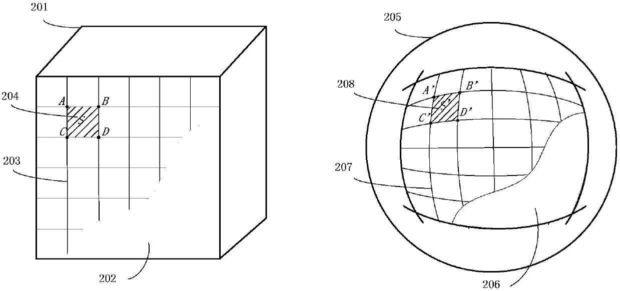
[0125] Step S101, creating a cube, wherein the surface area of ​​the cube is the same as the surface area of ​​the sphere where the spherical image is located. Divide the spherical image into surfaces by cubic spherical projection. This embodiment adopts a cube, and any regular polygon, polygon, etc. can be used in this embodiment. But in terms of calculation and utility, regular polygons including cubes have the best utility.

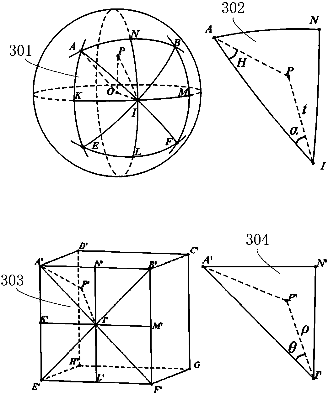
[0126] The specific segmentation of the spherical image further includes step S1011, setting the polyhedron in the sphere where the spherical image is located, and taking the center of the sphere as the center point.

[0127] Step S1012, mapping each vertex and edge of the polyhedron to a spherical image.

[0128] Step S1013, each vertex and edge mapped to the spherical image divides the spherical image into multiple surfaces.

[0129] ...

Embodiment 2

[0162] The method for projecting a spherical image or video image in this embodiment is based on the projection method in Embodiment 1, and further divides and maps the surface projected from the spherical surface to a cube, thereby further improving the distribution uniformity of pixels. The specific method flow is as follows:

[0163] Step S201, creating a cube, wherein the surface area of ​​the cube is the same as the surface area of ​​the sphere where the spherical image is located. Divide the spherical image into surfaces by cubic spherical projection.

[0164] The specific segmentation of the spherical image further includes step S2011, setting the polyhedron inside the sphere where the spherical image is located, and taking the center of the sphere as the center point.

[0165] Step S2012, mapping each vertex and edge of the polyhedron to a spherical image.

[0166] Step S2013, each vertex and edge mapped to the spherical image divides the spherical image into multipl...

Embodiment 3

[0182] The method for projecting a spherical image or video image in this embodiment is based on the projection method in Embodiment 2, and again divides and maps the surface projected from the spherical surface to a cube, thereby improving the uniformity of pixel distribution. The specific method flow is as follows:

[0183] Step S301, mapping each vertex and edge of the polyhedron to a spherical image.

[0184] Step S302, each vertex and edge mapped to the spherical image divides the spherical image into multiple surfaces.

[0185] Step S303, through the Snyder transformation, respectively establish the mapping relationship between each surface of the spherical image and each surface of the polyhedron. The mapping method is the same as step S202 in Embodiment 2, and will not be repeated here.

[0186] Step S304, perform the following steps for each pair of the surface of the spherical image and the face of the polyhedron that have a mapping relationship:

[0187] S3041. D...


PUM


Abstract

The invention discloses a projection method and back projection method for panoramic videos and pictures. The projection method comprises: a polyhedron is used for projection to a spherical surface and a spherical image is divided into a plurality of surfaces; with mapping transformation, a mapping relationship between each surface of the spherical image and each face of the polyhedron is established; and pixels of all surfaces of the spherical image are projected to the faces of the polyhedron in the mapping relationship. Besides, the back projection method includes: projection to a sphericalsurface is carried out by a polyhedral image and the spherical surface is divided into a plurality of surfaces; on the basis of mapping transformation, a mapping relationship between each surface ofthe polyhedral image and each face of the spherical surface is established; and pixels of all surfaces of the polyhedral image are projected to the surface of the spherical surfaces in the mapping relationship. According to the invention, on the basis of the panoramic image segmentation and polyhedral projection, pixel distribution becomes uniform, so that a problem of image quality reduction caused by panoramic image projection is solved.

Description

technical field [0001] The invention relates to a video and picture projection method and a back projection method, in particular to a panoramic video and picture projection method and a back projection method. Background technique [0002] Virtual reality (Virtual Reality, referred to as VR) technology is currently the most popular technology field, especially immersive virtual reality (Immersive Virtual Reality). The head position information is fed back to the host, and the host then sends the video in the direction of the user's perspective to the display. The user can change the head position at will to obtain scenes with different perspectives, as if they were on the scene, achieving a high degree of immersion. [0003] Browsing videos and pictures in a virtual reality environment is different from browsing on two-dimensional flat screens such as TVs and mobile phones. Since the user is in a virtual three-dimensional environment, the user can change the viewing angle t...

Claims


Application Information

Patent Timeline
Patent Type & Authority Applications(China)
IPC IPC(8): H04N9/31G06F3/01G03B37/04G02B13/06
CPCH04N9/31H04N9/3147G02B13/06G03B37/04G06F3/013
Inventor 金怡泽仲伟昆其他发明人请求不公开姓名
Owner 上海微湃电子科技有限公司
Why Eureka
Try Eureka