
Linear electromagnetic wave plasma source and plasma processing device using same

A plasma and processing device technology, which is applied in the field of plasma processing devices, can solve the problems of reduced electromagnetic wave intensity and efficiency, and the inability to maintain electromagnetic wave electromagnetic wave intensity uniformly, and achieve the effects of reduced attenuation, cooling effect, and increased strength

Active Publication Date: 2020-08-14
KOREA INST OF FUSION ENERGY
View PDF16 Cites 0 Cited by
  • Summary
  • Abstract
  • Description
  • Claims
  • Application Information

AI Technical Summary

Problems solved by technology

In this case, the magnetron is installed only on one side, and there is a problem that the intensity of the electromagnetic wave at the inflow part into which the electromagnetic wave flows cannot be maintained uniformly. The plasma source is installed outside the chamber in a manner separated from the chamber. Therefore, there is a problem that the strength and efficiency of electromagnetic waves transmitted to the processed object located inside the chamber are reduced.

Method used


Image

  • Linear electromagnetic wave plasma source and plasma processing device using same
  • Linear electromagnetic wave plasma source and plasma processing device using same
  • Linear electromagnetic wave plasma source and plasma processing device using same

Examples


Embodiment Construction

[0030] Detailed matters related to the above-mentioned purpose and technical configuration of the present invention and their accompanying effects can be more clearly understood from the following detailed description based on the accompanying drawings of the specification of the present invention. However, this does not limit the present invention to a specific disclosed form, and it should be understood that all changes, equivalent technical solutions, and replacement technical solutions are included in the idea and technical scope of the present invention. In describing the respective drawings, similar reference numerals are assigned to similar structural elements.

[0031] The terms used in this specification are for describing specific embodiments only, and do not limit the present invention. Expressions in the singular include subordinate expressions unless the context clearly indicates otherwise. It should be understood that throughout the specification, terms such as ...


PUM


Abstract

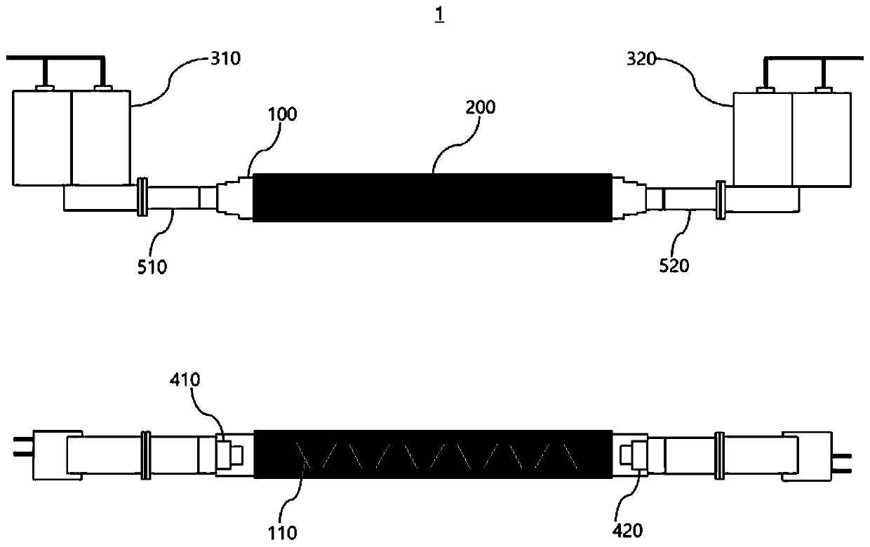
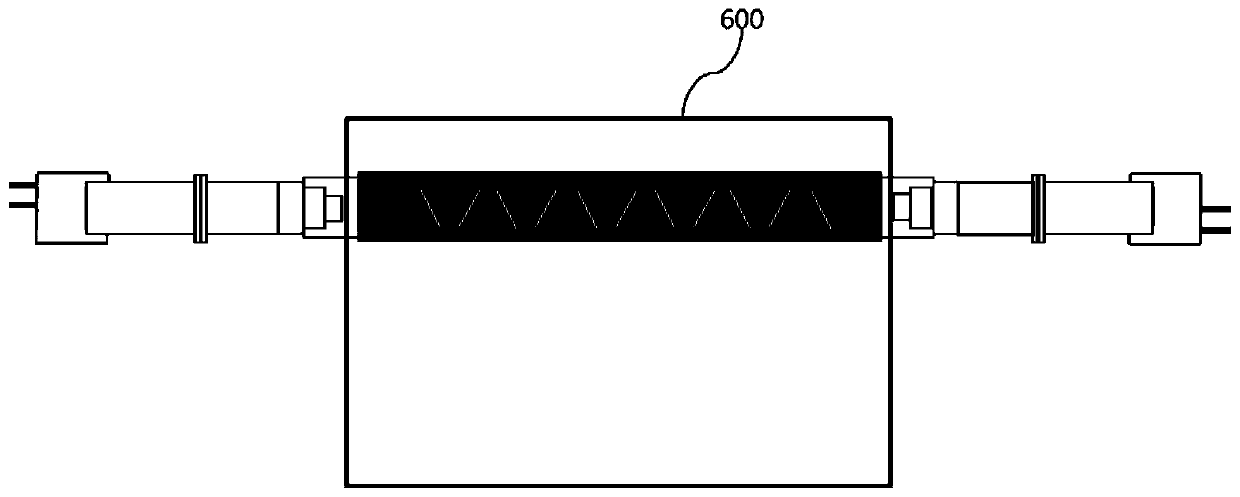
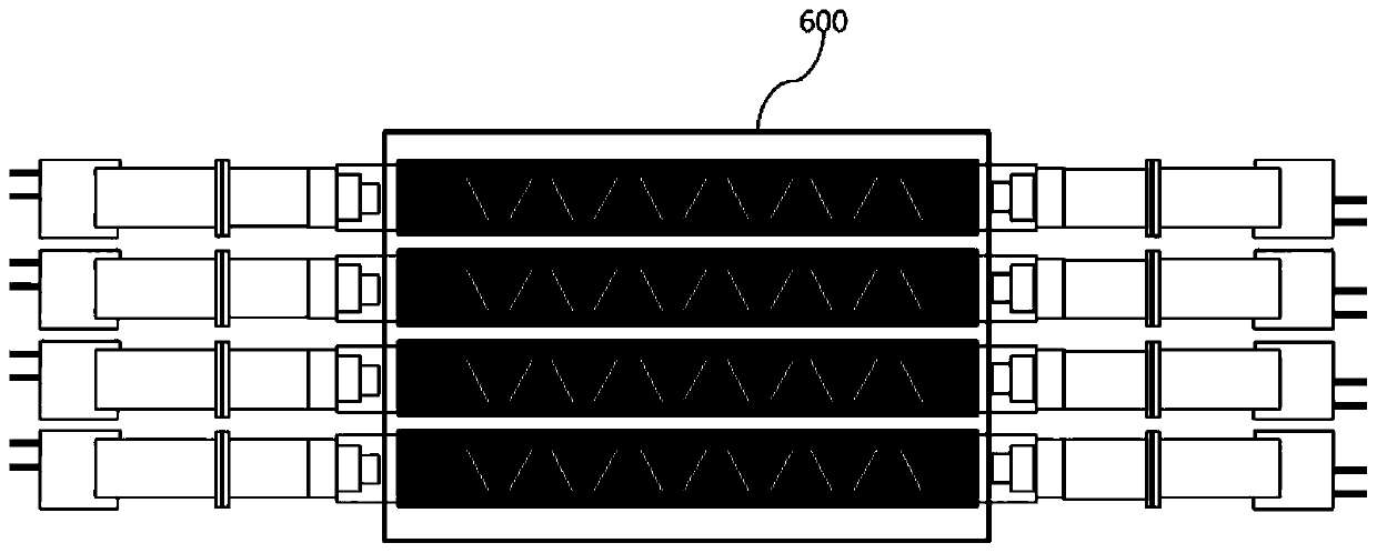
The linear electromagnetic wave plasma source and the plasma processing device using the same of the present invention include: a long cylindrical waveguide; a dielectric layer surrounding the cylindrical waveguide in such a manner as to be in contact with the outer surface of the cylindrical waveguide; and a first magnetron and a second magnetron for supplying electromagnetic waves to both ends of the cylindrical waveguide, and the cylindrical waveguide includes two or more slits formed along the longitudinal direction. If such a linear electromagnetic wave plasma source and a plasma processing apparatus using the same are used, the thickness of the dielectric layer provided to maintain the pressure difference between the inside and outside of the circular waveguide can be reduced as the circular waveguide is used. Therefore, the attenuation of the electromagnetic wave radiated from the circular waveguide is reduced, and the intensity of the electromagnetic wave can be increased.

Description

technical field [0001] The present invention relates to a linear electromagnetic wave plasma source, that is, a plasma processing apparatus using the same. More specifically, the present invention relates to a plasma source and a plasma processing apparatus using the plasma source for an object to be processed: a circle with open sides is provided. A circular waveguide and a circular dielectric tube that surrounds it in a close-fitting manner. Electromagnetic waves are transmitted to the interior of the circular waveguide through multiple magnetrons located on both sides of the circular waveguide, and the multiple magnetrons formed in the circular waveguide Each slit emits electromagnetic waves through the dielectric layer, thereby generating plasma. Background technique [0002] Generally, plasma is defined as the fourth substance that is not solid, liquid and gas, and is a part of the gas that is ionized. There are free electrons, cations, neutrals and central molecules in...

Claims


Application Information

Patent Timeline
Patent Type & Authority Patents(China)
IPC IPC(8): H05H1/46
CPCH05H1/46H05H1/4645H01J37/32229H01J37/32522H01J37/32899H05H1/4622
Inventor 刘铉钟
Owner KOREA INST OF FUSION ENERGY
Learn More