
Method and system for vehicle Anti-collision pre-warning based on binocular stereo vision

A binocular stereo vision and anti-collision technology, which is applied in the field of automobile anti-collision technology, can solve the problems of scalability and poor versatility, and achieve the effects of strong anti-interference ability, reduced front-end calculation amount, and low precision requirements

Active Publication Date: 2018-07-03
UISEE TECH BEIJING LTD
View PDF9 Cites 14 Cited by
  • Summary
  • Abstract
  • Description
  • Claims
  • Application Information

AI Technical Summary

Problems solved by technology

[0008] Patent Document 2 also uses a machine learning-based recognition method for detection, which relies heavily on training samples and artificially designed features. The scene areas encountered during driving vary widely, and it cannot be detected when it encounters situations that do not exist in the training samples. The scalability and versatility are not strong, but the distance calculation can achieve more accurate results through binoculars

Method used

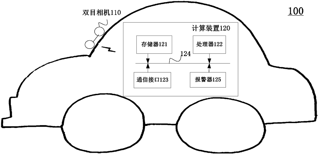

Image

  • Method and system for vehicle Anti-collision pre-warning based on binocular stereo vision
  • Method and system for vehicle Anti-collision pre-warning based on binocular stereo vision
  • Method and system for vehicle Anti-collision pre-warning based on binocular stereo vision

Examples


Embodiment Construction

[0036] In order to enable those skilled in the art to better understand the present invention, the present invention will be further described in detail below in conjunction with the accompanying drawings and specific embodiments.

[0037] First an explanation of the terms used in this paper is given.

[0038] Disparity map: The disparity map is based on any image in the image pair, its size is the size of the reference image, and the element value is an image of the disparity value. The disparity map contains the distance information of the scene. The disparity map can be calculated from the left and right images captured by the binocular camera. The coordinates of a certain point in the ordinary two-dimensional disparity map are represented by (u, v), where u is the abscissa and v is the ordinate; the pixel value of the pixel at the point (u, v) is represented by d(u, v), The pixel value represents the disparity at that point (u,v). Image matching, which extracts disparit...


PUM


Abstract

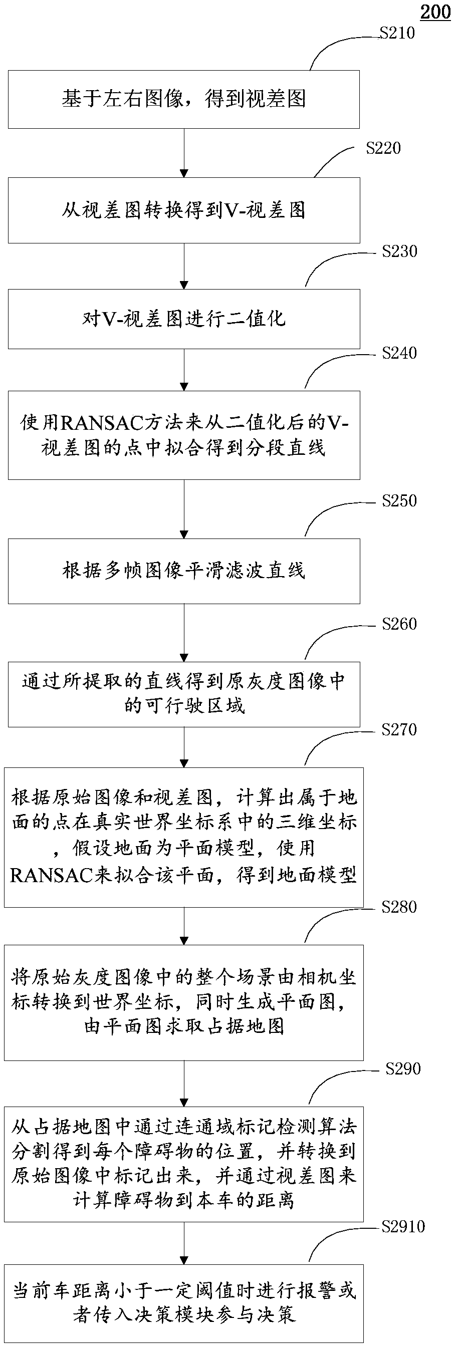
A method and system for vehicle anti-collision pre-warning based on a binocular stereo vision, comprising: acquiring left and right images by means of a binocular camera mounted on a vehicle body, andobtaining a disparity image based on the left and right images (S210); converting the disparity image to obtain a V-disparity image (S220); binarizing the V-disparity image (S230); fitting to obtaina segment straight line from points of the binarized V-disparity image using a RANSAC method (S240); smoothing and filtering the straight line according to multiple frames of images (S250); obtainingan accessible region in an original grayscale image by means of the extracted straight line (S260); according to the original image and the disparity image, calculating a three-dimensional coordinateof a point on the ground in a real-world coordinate system, and assuming that the ground is a planar model, fitting the plane using RANSAC so as to obtain a ground model (S270); converting the entirescene in the original grayscale image from a camera coordinate into a world coordinate while generating a plane graph, and obtaining an occupied map from the plane graph (S280); dividing the occupiedmap by means of a connected domain labeling detection algorithm to obtain the position of each obstacle, converting same into the original image for marking, and calculating the distance from the obstacle to this vehicle through the disparity image (S290); and when a current vehicle distance is less than a certain threshold value, giving an alarm or introducing a decision-making module for participation in decision-making (S2901). The method is adapted to various pavements and road conditions, has a low requirement for disparity image precision, does not rely on data, and is not affected by anartificial design.

Description

technical field [0001] The present invention generally relates to automobile automatic driving technology, and more specifically relates to automobile collision avoidance technology based on binocular stereo vision. Background technique [0002] Accurate and real-time anti-collision warning has important application significance, especially in assisted driving safety warning and automatic control of automatic driving. For example, in automatic driving, anti-collision warning can reduce accidents as much as possible and avoid personal injury. and property damage; in automatic driving, the more accurate the anti-collision warning, the higher the safety. [0003] At present, there are mainly methods for anti-collision warning. One is based on the laser radar sensor or millimeter wave radar. First, the calibration is performed, and the area below a certain threshold is judged as the ground. The cost of the laser radar required by this method is very high, and it is difficult to ...

Claims


Application Information

Patent Timeline
IPC IPC(8): G06K9/00
CPCG06V20/56G06V20/58G06T7/00
Inventor 李斌赵勇
Owner UISEE TECH BEIJING LTD
Learn More