Forge rolling machine directly driven by frameless permanent magnet synchronous motors

A technology for permanent magnet synchronous motors and roll forging machines, which is applied in the direction of driving devices, electromechanical devices, and electrical components for metal rolling mills. There are many transmission parts, etc., to achieve the effect of reducing energy loss, improving work efficiency, and high-power energy output

Pending Publication Date: 2018-07-06
HUBEI HUANYEE ELECTROMAGNETIC EQUIP ENG TECH CO LTD
View PDF6 Cites 5 Cited by
  • Summary
  • Abstract
  • Description
  • Claims
  • Application Information

AI Technical Summary

Problems solved by technology

At present, the drive of the roll forging machine is generally composed of a motor, a V-belt, a reduction box, and a transmission gear. There are many intermediate transmission parts, the power loss is large, and the transmission accuracy is low; The wedges or threads at both ends are manually adjusted, and the moving positions of the two ends are not easy to keep consistent in actual operation. These problems are not conducive to the precise processing of rolled parts

Method used


Image

  • Forge rolling machine directly driven by frameless permanent magnet synchronous motors
  • Forge rolling machine directly driven by frameless permanent magnet synchronous motors
  • Forge rolling machine directly driven by frameless permanent magnet synchronous motors

Examples


Embodiment 1

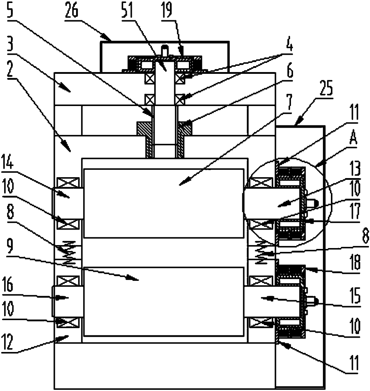
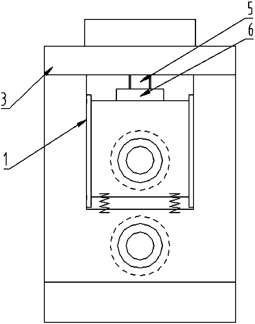
[0038] Such as Figure 1-6 Shown: a roll forging machine directly driven by a frameless permanent magnet synchronous motor, including a sliding guide rail 1, an upper roller support 2, a frame 3, a bearing 4, a screw rod 5, a nut 6, an upper roller 7, Compression spring 8, lower roller 9, roller bearing 10, motor bracket 11, lower roller support 12, the upper roller support 2 is connected with the sliding guide rail 1, and the upper roller 7 is driven by the upper roller The shaft 13 and the upper roller shaft 14 are installed on the upper roller support 2, and the lower roller 9 is installed on the lower roller support 12 by the lower roller drive shaft 15 and the lower roller axle 16, and the upper roller support A compression spring 8 is arranged between the seat 2 and the lower roller support 12; the screw mandrel 5 is installed on the frame 3; the upper roller drive shaft 13 and the lower roller drive shaft 15 are respectively connected with a second A frameless permanen...

Embodiment 2

[0051] Such as Figure 7 As shown, a roll forging machine directly driven by a frameless permanent magnet synchronous motor. It is driven by a single machine, wherein the lower roller drive shaft 15 is fixedly connected to the second frameless permanent magnet synchronous motor 18, and a transmission part 30 is used between the upper roller 7 and the lower roller 9 driven by the linear motor The intermediate transmission part ensures the synchronous movement of the rollers to ensure the precise forming of the workpiece, and the intermediate transmission part can be gear transmission or chain transmission.

Embodiment 3

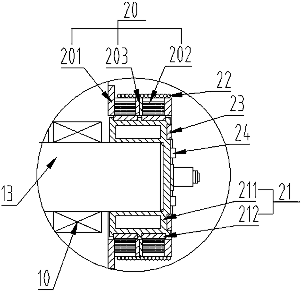
[0053] Such as Figure 8-10 As shown, a roll forging machine directly driven by a frameless permanent magnet synchronous motor. The stator assembly 20 described in this example includes a disk-shaped stator base 204 , a second stator core 205 , and a second stator winding 206 , and the second stator core 205 is an integrally formed ring-shaped disk structure. The rotor assembly 21 includes a disk-shaped rotor base 213 and a disk-shaped magnetic steel substrate 214 .

[0054] The disk-shaped stator base 204 , the second stator core 205 , the second stator winding 206 , the disk-shaped rotor base 213 , and the disk-shaped magnetic steel substrate 214 are combined into a frameless permanent magnet synchronous disk motor 28 .

[0055] After the power is turned on, the disc-shaped magnetic steel substrate 214 provides an axial rotating magnetic field for the second stator core 205, and the frameless permanent magnet synchronous disc motor 28 drives the upper roller 7 and the lower...


PUM


Abstract

The invention discloses a forge rolling machine directly driven by frameless permanent magnet synchronous motors. An upper rolling wheel drive shaft and a lower rolling wheel drive shaft are connectedwith the first frameless permanent magnet synchronous motor, and the first frameless permanent magnet synchronous motor is fixedly installed on an upper rolling wheel support and a lower rolling wheel support through motor brackets; a screw rod shaft of a screw rod is connected with the second frameless permanent magnet synchronous motor, the other end of the screw rod is connected to the upper rolling wheel support through a nut, and the second frameless permanent magnet synchronous motor is fixed to a machine frame through a motor bracket. The frameless permanent magnet synchronous motors are adopted as rolling wheel drive motors, so that drive intermediate links like a transmission part are reduced, the drive mode and structure are simplified, the drive efficiency is improved, direct driving of rolling wheels is achieved, the running reliability of the machine can be improved, the manufacturing cost and the usage cost are reduced, and the energy loss is reduced.

Description

technical field [0001] The invention relates to the field of forging machinery and equipment, in particular to a roll forging machine directly driven by a frameless permanent magnet synchronous motor. Background technique [0002] The roll forging machine is mainly used for pre-forging of forgings, and can also be used for final forging. The essence of roll forging deformation is the rolling extension of the blank. At present, the drive of the roll forging machine is generally composed of a motor, a V-belt, a reduction box, and a transmission gear. There are many intermediate transmission parts, the power loss is large, and the transmission accuracy is low; The wedges or threads at both ends are manually adjusted, and the moving positions of the two ends are not easy to keep consistent in actual operation. These problems are not conducive to the precise processing of rolled parts. [0003] Therefore, there is an urgent need for a new driving method to solve the above techni...

Claims


Application Information

Patent Timeline
Patent Type & Authority Applications(China)
IPC IPC(8): B21B35/00H02K7/06
CPCH02K7/06B21B35/00
Inventor 黄诚杨勇强
Owner HUBEI HUANYEE ELECTROMAGNETIC EQUIP ENG TECH CO LTD
Why Eureka
Try Eureka