
Ultrasonic welding device

An ultrasonic welding and welding head technology, applied in welding equipment, non-electric welding equipment, metal processing equipment, etc., can solve the problems that materials can only be supplied from the left and right directions of the machine head, the scope of application is small, and the size cannot be too large. The effect of reducing design cost, wide application range and improving production efficiency

Pending Publication Date: 2018-07-06
KEPU ULTRASONIC ELECTRONICS TECHCAL
View PDF0 Cites 2 Cited by
  • Summary
  • Abstract
  • Description
  • Claims
  • Application Information

AI Technical Summary

Problems solved by technology

[0002] In the existing ultrasonic welding equipment, the ultrasonic transducer system is installed longitudinally inside the machine head, and the welding head is installed longitudinally and protrudes outside the machine head. The limitation of this device is that the radial welding section size of the ultrasonic welding head cannot be too large , when the welding head moves to the lowest end during the welding process, the welding surface is still higher than the bottom surface of the machine head, so the material can only be fed from the left and right directions of the machine head. There are certain limitations in the welding process, and the scope of application is small

Method used


Image

  • Ultrasonic welding device
  • Ultrasonic welding device
  • Ultrasonic welding device

Examples


Embodiment 1

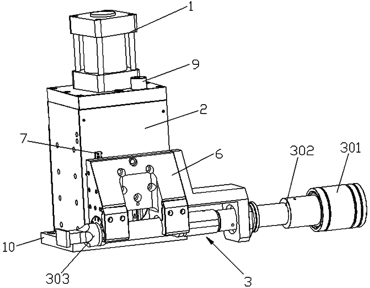
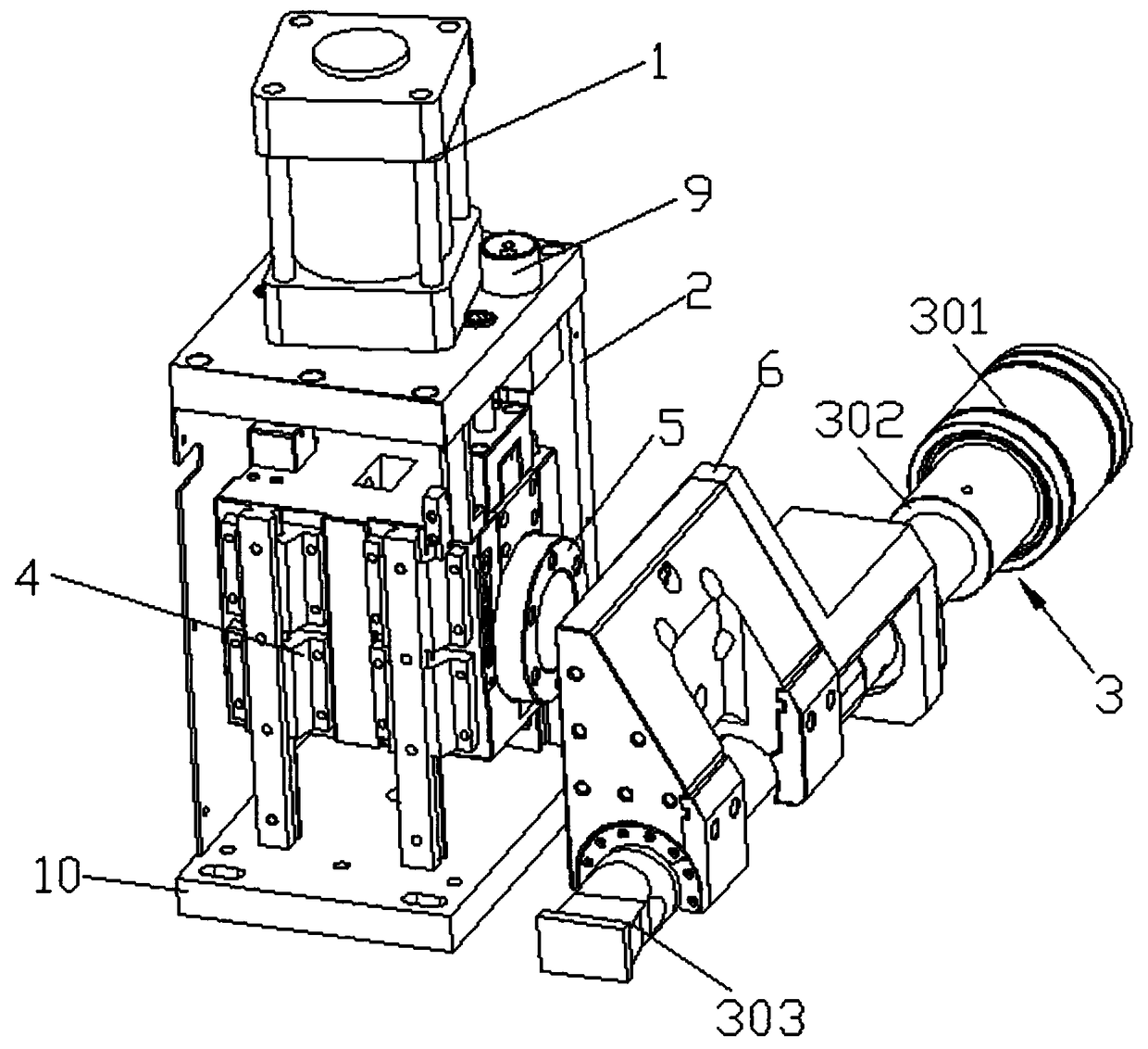
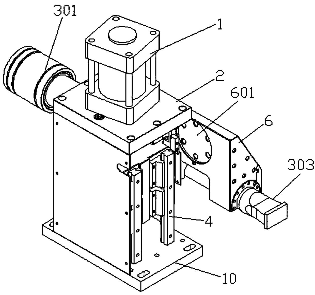
[0022] Such as Figure 1~4 As shown, the ultrasonic welding device of the present invention mainly includes a driving mechanism 1 , a machine head 2 and a transducer assembly 3 , and the machine head 2 can be installed on a base 10 . The machine head 2 is provided with a bracket 4, and the bracket 4 is connected with the power output end of the driving mechanism 1, that is, the driving mechanism 1 drives the bracket 4 to move up and down. The transducer assembly 3 is arranged in front of the machine head 2 and is fixedly connected to the bracket 4. The fixed connection method is as follows: a sleeve 5 is arranged on the bracket 4, and the transducer assembly 3 is supported by a mounting frame 6, and the mounting frame 6 A nesting portion 601 matching the sleeve 5 is provided on the top, so that the sleeve 5 is nested and fixed with the nesting portion 601 by screws.

[0023] The transducer assembly 3 includes a transducer 301, a horn 302 and a welding head 303 connected in se...

Embodiment 2

[0027] Such as Figure 5 As shown, the only difference from Embodiment 1 is that the welding head 303 with the welding position on the right side is selected, and the welding head 303, the horn 302 and the transducer 301 are installed in sequence from right to left, and the incoming materials can be transferred from the machine The right side of head 2 is used for vertical or horizontal incoming material production welding. Other structures are the same as those in Embodiment 1, and will not be repeated here.

Embodiment 3

[0029] Such as Figure 6 As shown, the only difference from Embodiment 1 is that the welding head 303 with the welding position in the middle is selected, and the welding head 303, the horn 302 and the transducer 301 are installed in sequence from left to right, and the incoming material can be obtained from the machine head. 2. Bottom longitudinal or horizontal incoming material production welding. Other structures are the same as those in Embodiment 1, and will not be repeated here.

[0030] Working principle of the present invention:

[0031] The ultrasonic welding device of the present invention is used in conjunction with the lower ultrasonic welding seat (lower mold or lower sonotrode or lower welding head) and an ultrasonic generator, and the ultrasonic generator is electrically connected to the transducer 301 . The transducer 301 converts the high-frequency electric energy emitted by the ultrasonic generator into mechanical motion of the same frequency. The horn 302 ...


PUM


Abstract

The invention relates to the technical field of welding, in particular to an ultrasonic welding device. The ultrasonic welding device mainly comprises a driving mechanism, a head portion and an energyexchange component and is characterized in that a supporting frame is arranged in the head portion and connected with a power output end of the driving mechanism, and the energy exchange component isarranged in front of the head portion and fixedly connected with the supporting frame. By structural optimization and improvement, a welding head is capable of flexibly adapting to incoming materialdirections in a welding process, adaptability is achieved no matter materials come from a longitudinal direction or a transverse direction and from the bottom of the head portion or left and right sides of the head portion, defects in use of traditional welding equipment are well overcome, and more supply choices are provided in an ultrasonic welding process. Especially in application to integration of automatic equipment, a wide application range is realized, production efficiency is greatly improved, a design structure of the automatic equipment is simplified, and design cost of the automatic equipment is reduced.

Description

technical field [0001] The invention relates to the field of welding technology, in particular to an ultrasonic welding metal device. Background technique [0002] In the existing ultrasonic welding equipment, the ultrasonic transducer system is installed longitudinally inside the machine head, and the welding head is installed longitudinally and protrudes outside the machine head. The limitation of this device is that the radial welding section size of the ultrasonic welding head cannot be too large , when the welding head moves to the lowest end during the welding process, the welding surface is still higher than the bottom surface of the machine head, so the material can only be fed from the left and right directions of the machine head. There are certain limitations in the welding process, and the scope of application is small. Contents of the invention [0003] In view of the deficiencies in the prior art, the object of the present invention is to provide an ultrasoni...

Claims


Application Information

Patent Timeline
IPC IPC(8): B23K20/10B23K20/26
CPCB23K20/10B23K20/26
Inventor 雷广伟
Owner KEPU ULTRASONIC ELECTRONICS TECHCAL
Learn More