A new type of high-efficiency anaerobic fermentation equipment

An anaerobic fermentation, high-efficiency technology, applied in biochemical equipment and methods, bioreactor/fermenter combinations, bioreactors/fermenters for specific purposes, etc.

Active Publication Date: 2018-12-04
ANHUI WANLI FOODS CO LTD
View PDF4 Cites 0 Cited by
  • Summary
  • Abstract
  • Description
  • Claims
  • Application Information

AI Technical Summary

Problems solved by technology

[0002] Anaerobic fermentation refers to the stabilization of waste through the metabolic activities of microorganisms under anaerobic conditions, accompanied by changes in the production of methane and CO2. The liquefaction stage is mainly due to fermentation bacteria, including cellulolytic bacteria and proteolytic bacteria. , the acid-producing stage is mainly acetic acid bacteria, and the methanogenic stage is mainly methane bacteria. They degrade the products produced in the acid-producing stage into methane and CO2, and use the hydrogen produced in the acid-producing stage to reduce CO2 into methane. Anaerobic fermentation Influencing factors are: ratio of raw materials, carbon-nitrogen ratio of anaerobic fermentation should be 20-30, when the carbon-nitrogen ratio is 35, the production period will drop significantly; the temperature should be 35-40°C; It is absolutely necessary to maintain a weak alkaline environment. Its optimal pH range is 6.8-7.5, and the pH value is low. It increases CO2 greatly, produces a large amount of water-soluble organic matter and H2S, and the increase of sulfide content inhibits the growth of methanogens. growth, you can add lime to adjust the PH, but the traditional way of adding lime is to open the sealed cover and add it to the fermenter, which will affect the growth of anaerobic microorganisms, so it will have a great impact on fermentation

Method used


Image

  • A new type of high-efficiency anaerobic fermentation equipment
  • A new type of high-efficiency anaerobic fermentation equipment

Examples


Embodiment Construction

[0020] All features disclosed in this specification, or steps in all methods or processes disclosed, may be combined in any manner, except for mutually exclusive features and / or steps.

[0021] Any feature disclosed in this specification (including any appended claims, abstract and drawings), unless expressly stated otherwise, may be replaced by alternative features which are equivalent or serve a similar purpose. That is, unless expressly stated otherwise, each feature is one example only of a series of equivalent or similar features.

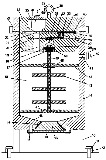
[0022] Such as Figure 1-2 As shown, a new type of high-efficiency anaerobic fermentation equipment of the device of the present invention includes a fermenter 44 fixedly installed on the support 10, and the fermenter 44 is provided with a fermentation chamber 51 with an opening facing upwards, and the side of the fermentation chamber 51 is An air outlet 41 communicating with the outside is arranged in the wall, an air guide tube 40 communica...


PUM


Abstract

The invention discloses novel efficient anaerobic fermentation equipment. The novel efficient anaerobic fermentation equipment comprises a fermentation tank which is fixedly mounted on a bracket, wherein a fermentation cavity with an upward opening is formed in the fermentation tank; an air outlet hole communicated with the outside is formed in a side wall of the fermentation cavity; an air guidepipe communicated with the air outlet hole is fixedly mounted on an outer wall of the fermentation tank; a valve is mounted on the air guide pipe; a stirring assembly is arranged in the fermentation cavity; the stirring assembly comprises a stirring shaft, a stirring blade, an upper supporting sleeve and a lower supporting sleeve; the stirring shaft is rotatably mounted in the upper supporting sleeve and the lower supporting sleeve through a bearing; supporting arms are fixedly mounted at the left and right sides of the upper supporting sleeve and the lower supporting sleeve; one end, far awayfrom the stirring shaft, of each supporting arm is fixedly mounted on an inner wall of the fermentation cavity; a first friction disc is fixedly mounted at the upper end of the stirring shaft; a sealing cover is mounted at the upper end of the fermentation cavity in a sealing and matching manner; a suspension arm is fixedly mounted at the center of the upper end face of the sealing cover.

Description

technical field [0001] The invention relates to the technical field of microbial fermentation, in particular to a novel high-efficiency anaerobic fermentation equipment. Background technique [0002] Anaerobic fermentation refers to the stabilization of waste through the metabolic activities of microorganisms under anaerobic conditions, accompanied by changes in the production of methane and CO2. The liquefaction stage is mainly due to fermentation bacteria, including cellulolytic bacteria and proteolytic bacteria. , the acid-producing stage is mainly acetic acid bacteria, and the methanogenic stage is mainly methane bacteria. They degrade the products produced in the acid-producing stage into methane and CO2, and use the hydrogen produced in the acid-producing stage to reduce CO2 into methane. Anaerobic fermentation Influencing factors are: ratio of raw materials, carbon-nitrogen ratio of anaerobic fermentation should be 20-30, when the carbon-nitrogen ratio is 35, the prod...

Claims


Application Information

Patent Timeline
Patent Type & Authority Patents(China)
IPC IPC(8): C12M1/107C12M1/02
CPCC12M21/04C12M27/02
Inventor 陈柏海
Owner ANHUI WANLI FOODS CO LTD
Why Eureka
Try Eureka