
Cooling water tank

A heat dissipation water tank and water tank cover technology, which is applied to the cooling of engine components, machines/engines, and engines, can solve problems such as bursting, and achieve the effect of improving safety and ensuring safe operation

Pending Publication Date: 2018-07-06
深圳光启梦想科技有限公司
View PDF0 Cites 2 Cited by
  • Summary
  • Abstract
  • Description
  • Claims
  • Application Information

AI Technical Summary

Problems solved by technology

[0003] Aiming at the problems existing in the related art, the purpose of the present invention is to provide a cooling water tank, wherein, by adding a buffer chamber connected to the cooling liquid chamber in the water tank, when the pressure in the cooling liquid chamber is too high, the excess pressure can be The discharge from the buffer chamber effectively solves the problem of bursting caused by excessive system pressure when the water tank is boiled, thus ensuring the safe operation of the engine cooling system

Method used


Image

  • Cooling water tank
  • Cooling water tank

Examples


Embodiment Construction

[0022] Embodiments of the present invention will be specifically described below in conjunction with the accompanying drawings. It should be noted that the following embodiments may be combined or partially replaced in any possible manner.

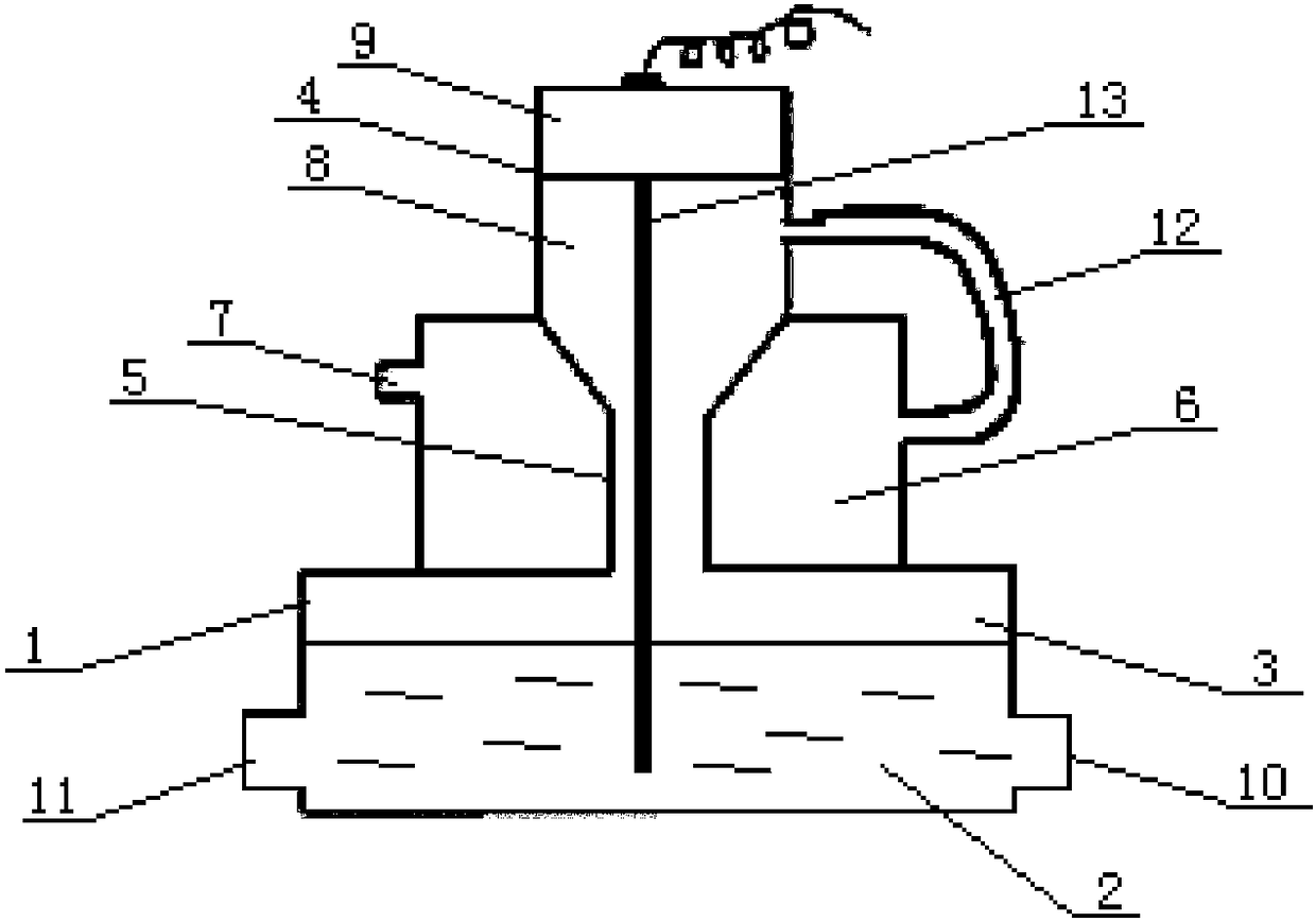
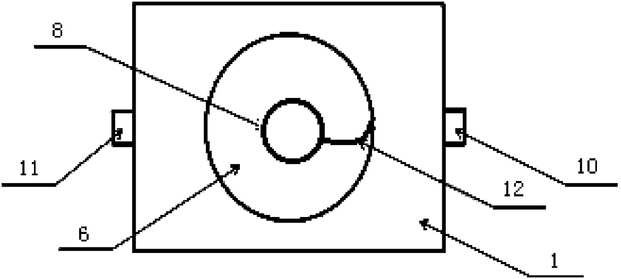
[0023] now refer to figure 1 , which shows a radiator tank according to an embodiment of the present invention. Such as figure 1 As shown, the cooling water tank is used for the cooling system of the engine, and includes a coolant chamber 1, the coolant chamber 1 includes a coolant chamber 3 for containing the coolant 2, and a cooling chamber 3 at the top of the coolant chamber 1 for filling the coolant 2 The coolant filling port 4, and the perfusion chamber 8 located below the cooling liquid filling port 4, wherein, as figure 1 As shown, the perfusion chamber 8 is located between the cooling liquid filling port 4 and the cooling liquid receiving chamber 3, thus the cooling liquid filling port 4 is in fluid communication with the coolin...


PUM


Abstract

The invention provides a cooling water tank. The cooling water tank comprises a cooling liquid chamber (1) and a buffer chamber (6); the cooling liquid chamber (1) comprises a cooling liquid containing cavity (3) for containing cooling liquid (2), a cooling liquid filling opening (4) in the top of the cooling liquid chamber (1) and a filling chamber (8) located below the cooling liquid filling opening (4), and the cooling liquid filling opening (4) and the cooling liquid containing cavity (3) are in liquid communication through the filling chamber (8); and the buffer chamber (6) is in liquid communication with the filling chamber (8) and is provided with a flow via opening (7) communicating to the atmosphere. The cooling water tank provided by the invention is used for an engine cooling system, by additionally arranging the buffer chamber communicating with the cooling liquid chamber in the water tank, when the pressure in the cooling liquid chamber is too high, excess pressure can bedischarged through the buffer chamber, the problem that a water tank explodes during boiling as the system pressure is too high is effectively solved, and thus safety running of the engine cooling system is ensured.

Description

technical field [0001] The invention relates to a heat dissipation water tank used for an engine heat dissipation system. Background technique [0002] The cooling system can ensure that the engine components maintain a suitable working temperature and ensure the reliability and good performance of their work. However, in high temperature weather, or when heat dissipation components fail, it is easy to cause the water temperature to be too high, that is, the water tank is boiled, and then the engine has poor heat dissipation and the temperature is too high. If it is not handled in time, it may cause the water tank to burst, or even cause serious machine damage accidents due to engine burnout. Contents of the invention [0003] Aiming at the problems existing in the related art, the purpose of the present invention is to provide a cooling water tank, wherein, by adding a buffer chamber connected to the cooling liquid chamber in the water tank, when the pressure in the cool...

Claims


Application Information

Patent Timeline
Patent Type & Authority Applications(China)
IPC IPC(8): F01P11/00F01P11/16F01P11/18
CPCF01P11/00F01P11/16F01P11/18
Inventor 不公告发明人
Owner 深圳光启梦想科技有限公司
Learn More