
Cleaning machine booster pump

A technology of booster pump and washing machine, applied in the direction of pump, pump control, pump components, etc., can solve the problems of large friction resistance of plunger, easy water leakage volume, complex structure, etc., to reduce volume, not easy to leak water, volume small effect

Pending Publication Date: 2018-07-06
SUZHOU KINGCLEAN PRECISION MACHINERY
View PDF0 Cites 1 Cited by
  • Summary
  • Abstract
  • Description
  • Claims
  • Application Information

AI Technical Summary

Problems solved by technology

[0004] A further object of the present invention is to solve the technical problem that the frictional resistance of the plunger is large when the booster pump is working
[0005] Another further purpose of the present invention is to solve the technical problems of complex structure, easy water leakage and large volume in the prior art that need to add an additional flow channel to arrange the safety valve

Method used


Image

  • Cleaning machine booster pump
  • Cleaning machine booster pump
  • Cleaning machine booster pump

Examples


Embodiment Construction

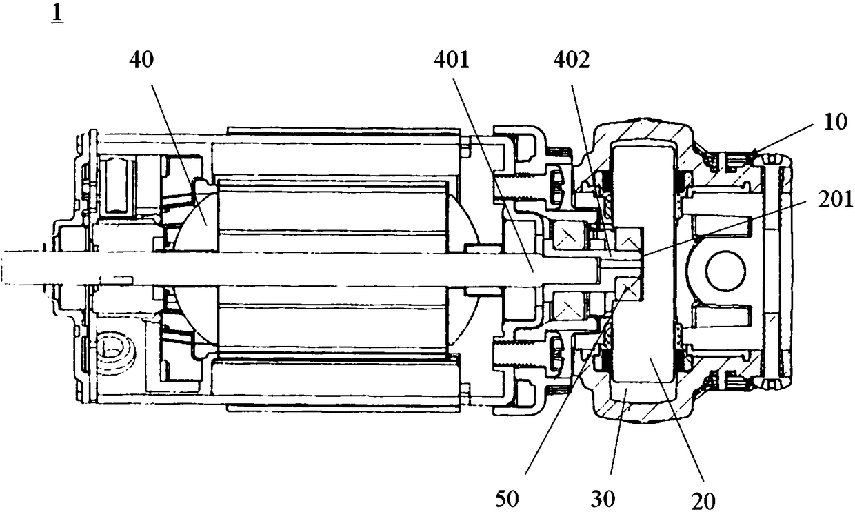
[0062] figure 1 A schematic structural diagram of a booster pump for a washing machine according to an embodiment of the present invention is shown. like figure 1 As shown, the washing machine booster pump 1 may include a housing 10 , a plunger 20 and an accommodating space 30 formed in the housing 10 . The plunger 20 is suspended in the accommodating space 30 . The accommodating space 30 extends along the axial direction of the plunger 20 . The plunger 20 divides the accommodation space 30 at its two ends into two pressurized chambers.

[0063] In one embodiment, such as figure 1 As shown, the plunger 20 includes a recess 201 . The recess 201 extends to the outer surface of the plunger 20 and is symmetrical with respect to a center line perpendicular to the axial direction of the plunger 20 . The washing machine booster pump 1 can also include a motor 40 . The motor 40 can be a DC motor, a series motor or a brushless motor. The motor 40 may include an output shaft 401...


PUM


Abstract

The invention provides a cleaning machine booster pump which comprises a shell, a plunger and a containing space formed in the shell. The plunger is suspended in the containing space, so that abrasionamong the plunger and other parts is avoided when the plunger reciprocates, the plunger is almost not abraded, and friction resistance is low. Besides, two times of output is realized by one time ofmovement of the plunger, transmission efficiency can be improved, the whole structure can be simplified, and the size can be miniaturized. The booster shell can be designed to be quite small, and thetransmission efficiency and the cleaning efficiency of the booster pump are much higher than those of a structure in the prior art.

Description

technical field [0001] The invention relates to the technical field of booster pumps, in particular to a booster pump for washing machines. Background technique [0002] At present, most booster pumps used in washing machines in the prior art are three-piston pumps, whose working principle is that one plunger unit controls one booster chamber, and the plunger realizes an effective output in each movement cycle. However, since each movement of the plunger can only drive a single movement of the inlet and outlet valves, the transmission efficiency is very low. In addition, the plunger in the booster pump of the prior art needs to be returned by components such as springs or connecting rods, which results in many components, complex structure, large volume, large vibration and heavy weight of the booster pump. Due to the centralized arrangement of the existing booster chambers, the structure of the pump head is complicated, which is not conducive to processing and assembly. ...

Claims


Application Information

Patent Timeline
IPC IPC(8): F04B17/03F04B53/14F04B53/02F04B53/16F04B53/10F04B49/20F04B53/00
CPCF04B17/03F04B49/20F04B53/00F04B53/02F04B53/10F04B53/14F04B53/16
Inventor 倪祖根
Owner SUZHOU KINGCLEAN PRECISION MACHINERY
Learn More