Self-cooling system of air compressor rotor borne by air foil bearing

A technology of foil bearings and air compressors, which is applied to mechanical equipment, machines/engines, liquid fuel engines, etc., can solve the problems of low cooling efficiency, uneven cooling and heat dissipation of air compressor rotors, and lack of intelligence, etc., to achieve extended Effective life, avoiding uneven cooling and heat dissipation, and improving stability

Inactive Publication Date: 2018-07-06
HUNAN UNIV
View PDF7 Cites 7 Cited by
  • Summary
  • Abstract
  • Description
  • Claims
  • Application Information

AI Technical Summary

Problems solved by technology

[0006] The purpose of the present invention is to propose a self-cooling system for rotors of air compressors supported by air foil bearings, to solve the problems of uneven cooling and heat dissipation of air compressor rotors, low cooling efficiency, and insufficient intelligence, and to realize fast and effective energy-saving cooling and heat dissipation

Method used


Image

  • Self-cooling system of air compressor rotor borne by air foil bearing
  • Self-cooling system of air compressor rotor borne by air foil bearing
  • Self-cooling system of air compressor rotor borne by air foil bearing

Examples


Embodiment 1

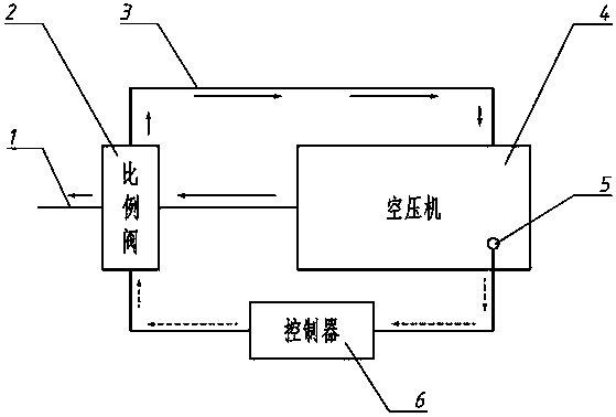
[0032] like figure 1 As shown, a self-cooling cooling system for an air compressor supported by an air foil bearing specifically includes a high-pressure gas delivery pipeline 1, a reinjection gas flow control valve 2, a high-pressure gas reinjection pipeline 3, an air compressor 4, Temperature sensor 5, PID controller 6. The reinjection gas flow control valve 2 is connected to the high pressure gas reinjection pipeline 3 in the high pressure gas delivery pipeline 1, and the other end of the high pressure gas reinjection pipeline 3 is connected to the air compressor 4; the temperature sensor 5 is set The surface temperature parameters of the rotor system of the air compressor are measured in the body of the air compressor 1; the PID controller 6 is connected to the temperature sensor 5 and the reinjection gas flow control valve 2 respectively.

[0033] The high-pressure gas generated by the operation of the air compressor 4 is delivered to the gas-consuming equipment by the h...

Embodiment 2

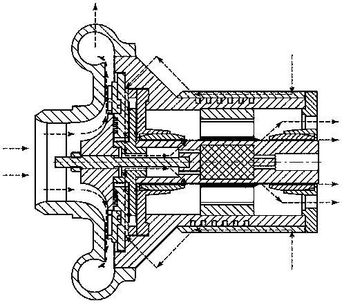
[0039] like Figure 4 , Figure 5 As shown, the execution scheme in this embodiment is generally the same as that in Embodiment 1, and the external cooling channels and control schemes are the same, but the difference lies in the composition of the internal cooling channels. In this embodiment, the air compressor 4 adopts the solid rotor 271 of the air compressor, so that the internal cooling channel is slightly changed. The high-pressure cooling gas no longer flows through the middle part of the thrust disc 25, but flows through the inside of the air compressor rotor, and only flows along the outer surface of the thrust disc 25 and the air compressor training rotor 271. Above, only this change is made to the internal cooling channel, and the rest of the channels are consistent with the first embodiment.

Embodiment 3

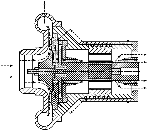
[0041] like Figure 6 , Figure 7 As shown, the execution scheme in this embodiment is generally the same as that in Embodiment 1, and the external cooling channels and control schemes are the same, but the difference lies in the composition of the internal cooling channels. In this embodiment, the air compressor 4 adopts the arrangement scheme of placing the thrust plate 252 behind, so that the internal cooling flow channel is changed. The high-pressure cooling gas passes through the uniformly distributed holes in the radial direction of the front end cover 22 and then reaches the outer circumferential surface of the front section of the compressor rotor 272, where the high-pressure cooling gas is divided into two parts. A part flows along the outer surface of the air compressor rotor 272 and passes through the radial air foil bearing 26 at the front end; a part enters the hollow part of the air compressor rotor 272 from the uniformly distributed radial channels at the front...


PUM


Abstract

The invention relates to the technical field of air compressors, and discloses a self-cooling system of an air compressor rotor borne by an air foil bearing. The system mainly comprises an air compressor outer cooling runner, a self-cooling control method and an air compressor inner cooling runner; the air compressor outer cooling runner achieves re-injection of part of high-pressure gas, the aircompressor inner cooling runner achieves flowing of high-pressure cooling gas from the front end of an air compressor to the back end of the air compressor along the air compressor rotor surface, andcooling of the air compressor rotor is achieved; the self-cooling control method finishes re-injection gas flow and air compressor rotor real-time temperature adaption closed-loop control. According to the self-cooling system of the air compressor rotor borne by the air foil bearing, the temperature of the air compressor rotor system can be effectively controlled, intelligent cooling is achieved,energy is saved, the air compressor rotor system is comprehensively cooled, the stability of the air compressor is improved, and the effective service life of the air compressor is prolonged.

Description

technical field [0001] Generally speaking, the present invention relates to the technical field of air compressors, and more specifically, relates to a rotor self-cooling system supported by air foil bearings of an air compressor. Background technique [0002] An air compressor (hereinafter referred to as an air compressor) is a mechanical device that compresses atmospheric air to provide a pressurized air source for air-consuming equipment. It is widely used in industrial production and people's lives. There are many types of air compressors. Centrifugal air compressors are mainly composed of rotors, stators, and impellers. After the gas enters the impeller of the air compressor, under the action of the impeller blades, it rotates at high speed with the impeller while rotating centrifugal force Under the action of the impeller, it flows to the outlet of the impeller, and is subjected to the diffusion effect of the impeller, its pressure energy and kinetic energy are both in...

Claims


Application Information

Patent Timeline
Patent Type & Authority Applications(China)
IPC IPC(8): F04D29/58F04D27/00F04D29/28
CPCF04D29/584F04D27/00F04D27/006F04D29/284
Inventor 吕鹏安林冯凯
Owner HUNAN UNIV
Why Eureka
Try Eureka