Camera lens optical axis calibration method and apparatus

A calibration method and lens technology, applied in the field of optics, can solve problems such as image misalignment, affecting the effect of image splicing and fusion, and achieve the effect of improving the presentation effect and user experience

Active Publication Date: 2018-07-06
GOERTEK OPTICAL TECH CO LTD
View PDF8 Cites 20 Cited by
  • Summary
  • Abstract
  • Description
  • Claims
  • Application Information

AI Technical Summary

Problems solved by technology

[0004] In order to solve the problem that the optical axes of the two fisheye lenses of the prior art camera are not on the same horizontal line, resulting in image misalignment and affecting the effect of image splicing and fusion, the present invention provides a method and device for calibrating the optical axis of the camera lens

Method used


Image

  • Camera lens optical axis calibration method and apparatus
  • Camera lens optical axis calibration method and apparatus
  • Camera lens optical axis calibration method and apparatus

Examples


Embodiment Construction

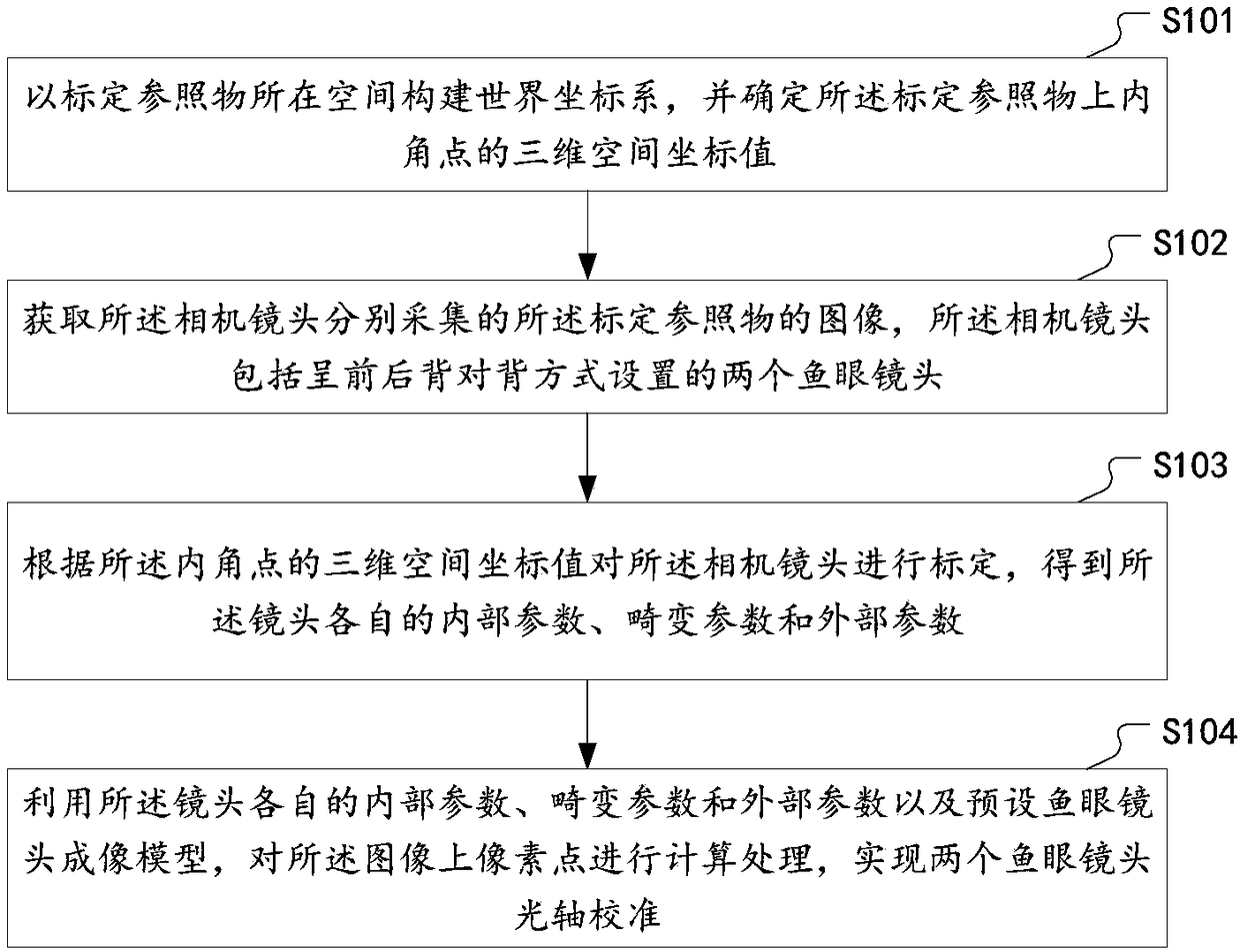
[0025] In order to solve the technical problems raised in the background technology, the inventors of the present application thought of calibrating the camera lens, and on the basis of camera calibration, added a lens optical axis calibration process to solve the problems that occurred during the actual loading process of the camera module. The deviation of the optical axis of the front and rear lenses is not on the same horizontal line, so as to reduce and avoid the occurrence of subsequent image stitching dislocation, and provide a basis for the subsequent image stitching and fusion algorithm to achieve good results, so as to obtain a more ideal panoramic image and user experience.

[0026] In order to make the object, technical solution and advantages of the present invention clearer, the implementation manner of the present invention will be further described in detail below in conjunction with the accompanying drawings.

[0027] figure 1 It is a schematic flow chart of a...


PUM


Abstract

The invention discloses a camera lens optical axis calibration method and apparatus. The method comprises the steps of building a world coordinate system by spaces where calibration reference objectsare located, and determining three-dimensional space coordinate values of internal corner points on the calibration reference objects; obtaining images of the calibration reference objects, collectedby camera lenses; according to the three-dimensional space coordinate values of the internal corner points, calibrating the camera lenses to obtain internal parameters, distortion parameters and external parameters of the lenses; and by utilizing the internal parameters, the distortion parameters and the external parameters of the lenses and a preset fisheye lens imaging model, performing calculation processing on pixel points on the images to realize optical axis calibration of two fisheye lenses. The corresponding camera lens optical axis calibration apparatus comprises a reference object determination unit, an image obtaining unit, a parameter calculation unit and an optical axis calibration unit. According to the technical scheme, the problem of subsequent image splicing dislocation caused by inaccurate back-to-back state of the front and back fisheye lenses of a camera is solved; the panoramic image effect is improved; and the usage experience of a user is improved.

Description

technical field [0001] The invention relates to the field of optical technology, in particular to a camera lens optical axis calibration method and device. Background technique [0002] With the development of technology, various electronic devices with camera functions emerge in an endless stream, and people's requirements for image quality are also getting higher and higher. Panoramic camera is a camera capable of shooting 360-degree panoramas at one time. It uses 360-degree panoramic captures to obtain scenes that cannot be captured by traditional cameras, bringing users a shocking panoramic experience. Panoramic cameras generally have two fisheye lenses, and the two fisheye lenses are set in a front-to-back back-to-back manner. The front lens captures the image of the object in front, and the rear lens captures the image of the rear object, and then stitches the two original images into a 360° panorama through an algorithm. image. [0003] When the panoramic camera is ...

Claims


Application Information

Patent Timeline
Patent Type & Authority Applications(China)
IPC IPC(8): G06T7/80G02B27/62G01M11/02
CPCG01M11/0221G02B27/62G06T7/80
Inventor 耿志远
Owner GOERTEK OPTICAL TECH CO LTD
Why Eureka
Try Eureka