A switched reluctance motor module and motor
A technology of switched reluctance motor and motor module, which is applied in the direction of AC motor control, synchronous motor for single-phase current, electromechanical device, etc. The density has not been fundamentally improved, and the output torque pulsation is large, achieving the effects of easy maintenance, low-cost safety redundancy combination, and high power density
- Summary
- Abstract
- Description
- Claims
- Application Information
AI Technical Summary
Problems solved by technology
Method used
Image
Examples
Embodiment 1
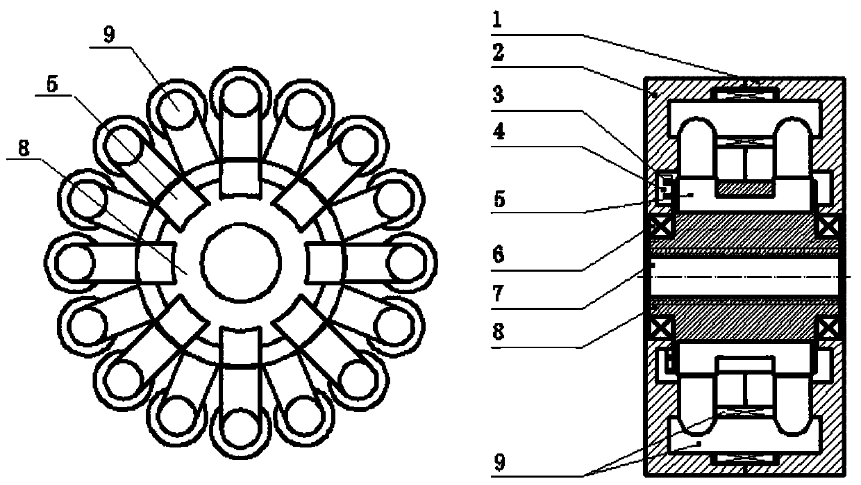
[0045] In this embodiment, the switched reluctance motor module adopts an axial excitation method.
[0046] The rotor assembly includes a rotor body 8 on which a plurality of rotor salient poles 5 are uniformly arranged along its circumferential surface. The salient poles of the rotor 5 are U-shaped or C-shaped rotor cores, and the center line of the two protruding ends of the rotor core is parallel to the central axis of the rotor body 8 and installed along the central axis of the rotor body 8 .
[0047] The stator assembly 9 includes a plurality of stator salient poles, and the stator salient poles include a stator core and a stator coil fixedly installed on the stator core. The stator core of the stator salient pole is an inverted U-shaped or inverted C-shaped stator core, and the stator coil is wound on the upper transverse section of the inverted U-shaped or inverted C-shaped stator core. A line connecting the centers of the two protruding ends of the stator core is para...
Embodiment 2
[0062] Such as image 3 As shown, the difference from Embodiment 1 is that the switched reluctance motor of this embodiment adopts an independent excitation mode. The rotor salient pole 5 is a rotor core with a magnetic pot core structure, the stator salient pole stator core is a magnetic pot core structure stator core, and the stator coil is fixed on the central column of the magnetic pot stator core.
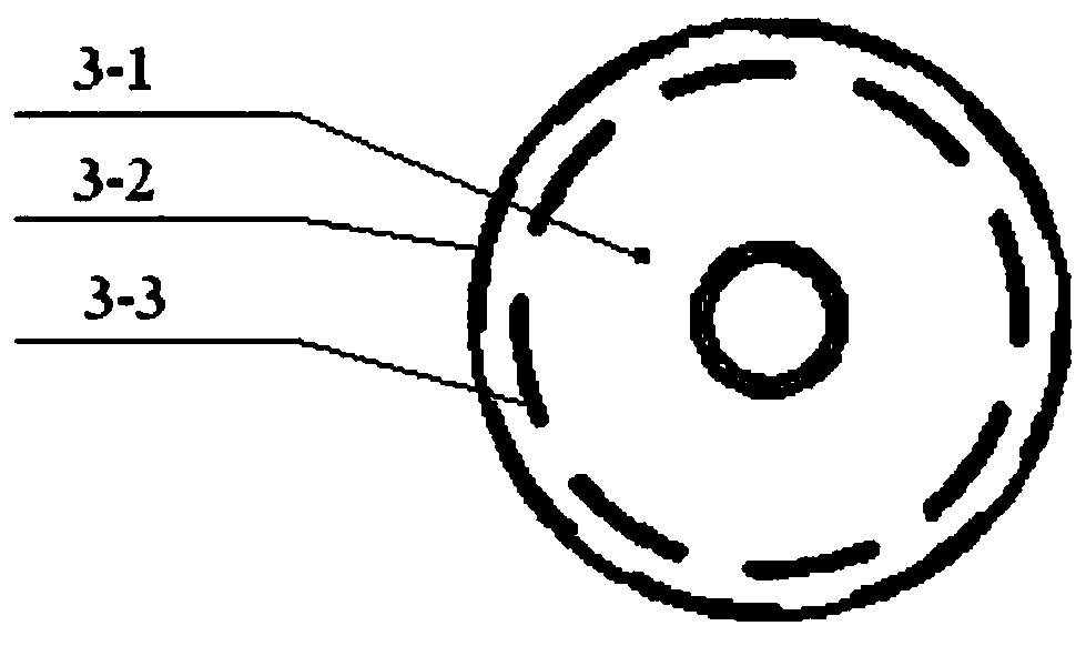
[0063] It should be noted that, in this embodiment, the number of rotor salient poles 5 is N, and N is an integer greater than or equal to 2. Correspondingly, when the two sensors are arranged along the radial direction of the circumference of the end cap, the inner code line 3-3 group and the outer code line 3-2 group of the code disc 3 both include N codes uniformly distributed along their respective circumferences. line, and the coding lines of the 3-3 groups of the inner coding line and the coding lines of the 3-2 group of the outer coding line are staggered at an angle o...
Embodiment 3
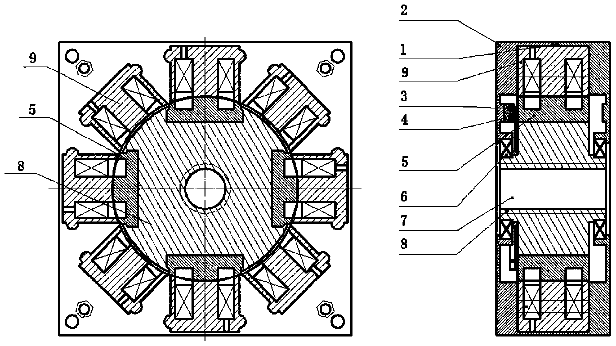
[0065] Such as Figure 4 As shown, the difference from Embodiment 1 is that the switched reluctance motor of this embodiment adopts a radial excitation method. The stator assembly 9 includes two first stator subassemblies and second stator subassemblies with the same structure; both the first stator subassembly and the second stator subassembly include M uniformly distributed along the central axis of the rotor body 8 as the axis of symmetry. Stator sub-salient poles 9-1, and the first stator sub-assembly and the second stator sub-assembly are arranged in parallel and staggered at an angle of π / M on the circumference outside the rotor assembly, the first stator sub-assembly and the second stator sub-assembly The projection number of all the stator salient poles 9-1 along the rotor axis direction is 2M, the magnetic poles of the adjacent stator salient poles 9-1 in the first stator subassembly are opposite in polarity, and the adjacent stator salient poles 9-1 in the second sta...
PUM
 Abstract
Description
Claims
Application Information
 - R&D
- Intellectual Property
- Life Sciences
- Materials
- Tech Scout
- Unparalleled Data Quality
- Higher Quality Content
- 60% Fewer Hallucinations
Browse by: Latest US Patents, China's latest patents, Technical Efficacy Thesaurus, Application Domain, Technology Topic, Popular Technical Reports.
© 2025 PatSnap. All rights reserved.Legal|Privacy policy|Modern Slavery Act Transparency Statement|Sitemap|About US| Contact US: help@patsnap.com


