
Low-temperature plasma generation device and gas processing system

A low-temperature plasma and generating device technology, applied in the direction of gas treatment, plasma, electrical components, etc., can solve the problems of small range of strong electric field, inability to output electric energy, and ineffective application

Inactive Publication Date: 2018-07-06
罗璐
View PDF14 Cites 3 Cited by
  • Summary
  • Abstract
  • Description
  • Claims
  • Application Information

AI Technical Summary

Problems solved by technology

[0004] There are also forms of negative oxygen ions, using DC high-voltage tip electric field discharge to excite ionized electrons to generate a small amount of negative oxygen ions, but the strength of the DC electric field is more than an order of magnitude weaker than that of the AC electric field of Dielectric Barrier Discharge (DBD). , and the DC electric field intensity is inversely proportional to the curvature of the discharge surface, the area of ​​the tip is small, resulting in a small range of strong electric field, therefore, the negative oxygen ions generated are very rare, and it is impossible to output higher electric energy to act on the treated gas, and the processing efficiency is extremely low
[0005] Ozone and hydroxyl radicals are extremely strong oxidants, which can break and dissolve the molecular chains of harmful pollutants in the air, and kill harmful microorganisms such as germs, viruses, fungi, etc., but they have not been effectively used yet.

Method used


Image

  • Low-temperature plasma generation device and gas processing system
  • Low-temperature plasma generation device and gas processing system
  • Low-temperature plasma generation device and gas processing system

Examples


Embodiment Construction

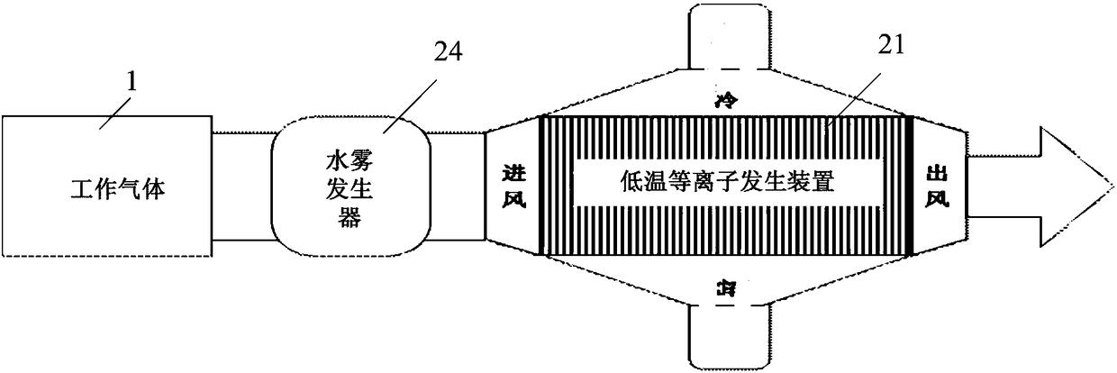
[0039] figure 1 A schematic diagram of an embodiment of a gas treatment system of the present application is shown.

[0040] As shown in the figure, the working gas 1 is processed by the gas treatment system 2 and becomes a clean gas 3 to be discharged and purified.

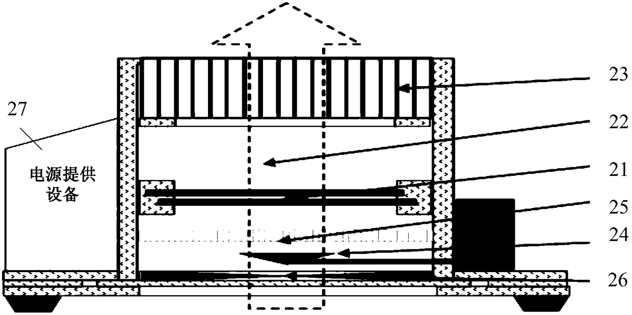
[0041] The gas treatment system 2 includes, for example, a low-temperature plasma generator 21 , an ozone reaction chamber 22 and / or a digestion catalytic zone 23 .

[0042] When the working gas 1 to be treated, such as air containing harmful components (such as formaldehyde, benzene, harmful microorganisms, organic pollutants, etc.), oxygen and moisture, circulates through the gas channel of the gas treatment system 2, in this channel, it is subjected to low-temperature plasma The bombardment of generating device 21 strong electric field low-temperature plasma, the harmful components in the gas are bombarded and decomposed, and the oxygen that accounts for more than 20% of the gas is ionized by strong electric ...


PUM


Abstract

The invention provides a low-temperature plasma generation device and a gas processing system. The low-temperature plasma generation device comprises at least one columnar discharging electrode component and at least another one same discharging electrode component or a columnar or grid-shape metal ground, wherein the at least one columnar discharging electrode component is formed by combining metal and a medium, the at least another one same discharging electrode component or the columnar or grid-shaped metal ground is arranged in parallel, the discharging electrode component is connected toa high-frequency and high-voltage power supply and is used for discharging the discharging electrode component or the columnar or grid-shaped metal ground arranged in parallel, so that low-temperatureplasma reaction is generated on a gas in a gap between the discharging electrode component and the same discharging electrode component or between the discharging electrode component and the columnaror grid-shaped metal ground. With the low-temperature plasma generation device provided by the scheme of the invention, enough large low-temperature plasma reaction gap is provided, so that a strongoxidization agent such as ozone is efficiently generated to eliminate a harmful substance in the gas, and an effect of killing the harmful substance in the gas for many times is achieved.

Description

technical field [0001] The present application relates to the field of gas treatment, in particular to a plasma generator and a gas treatment system. Background technique [0002] In order to remove harmful organic pollution atmosphere, unpleasant smell, and pathogenic microorganisms in the air, existing household air purifiers often use physical methods such as filter screen filtration and activated carbon adsorption. However, the microscopic size of the organic small molecules of the gaseous pollutants in the air is on the order of nanometers, and cannot be filtered out through the air flow filter. Adsorption is easy to accumulate and become saturated, and frequent replacement is required to increase the cost. [0003] In addition, there is a form of photocatalyst, which irradiates the surface coated with titanium dioxide by the ultraviolet component in the light source, and generates a small amount of hydroxyl radicals based on catalytic excitation. Because the proporti...

Claims


Application Information

Patent Timeline
Patent Type & Authority Applications(China)
IPC IPC(8): H05H1/24B01D53/32B01D53/76
CPCB01D53/323B01D53/76B01D2251/104B01D2259/818H05H1/2406
Inventor 罗璐江诗谦徐宝友刘国庆张延山
Owner 罗璐
Learn More