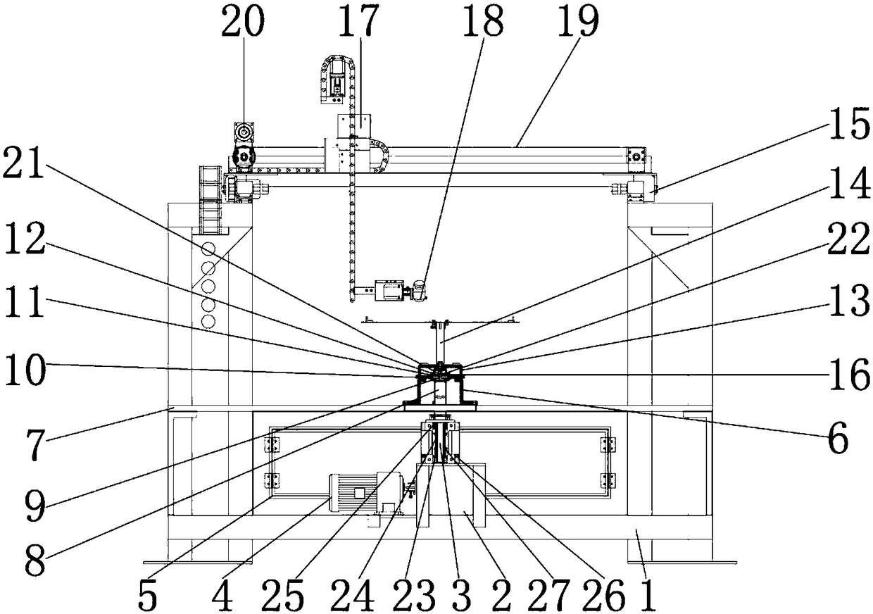
Novel vertical bipolar reciprocating die cutting machine

A die-cutting machine and vertical technology, which is applied in the field of new vertical bipolar reciprocating die-cutting machines, can solve problems such as hidden safety hazards and interrupt processing continuity, avoid waste, overcome instability of connecting parts, and improve accuracy Effect

Pending Publication Date: 2018-07-10
安吉腾新印刷厂
View PDF1 Cites 2 Cited by
  • Summary
  • Abstract
  • Description
  • Claims
  • Application Information

AI Technical Summary

Problems solved by technology

The indentation process is to use a creasing knife or a creasing die to press the line marks on the sheet through the action of pressure, or use a rolling wheel to bend and shape the sheet at a predetermined position. The working principle of the die-cutting machine is to use the die Cutters, steel knives, metal molds, steel wires (or templates carved from steel plates), apply a certain pressure through the embossing plate, and cut the printed matter or cardboard into a certain shape. If the entire printed matter is pressed into a single graphic The product is called die-cutting. If the steel wire is used to press marks on the printed matter or leave a bent groove, it is called indentation. If two templates are used, the mold is heated to a certain temperature, and the surface of the printed matter is ironed. Printing a pattern or font with a three-dimensional effect is called bronzing; if one substrate is used to laminate another substrate, it is called lamination; excluding the rest of the original product is called waste discharge. Commonly used die-cutting machines are divided into Flat die-cutting machine, rotary die-cutting machine and rotary flat die-cutting machine, in which the flat die-cutting machine mainly adopts a die-cutting bottom plate and a die-cutting plate set opposite to the die-cutting plate. There is a knife edge, and the raw materials are placed on the die-cutting bottom plate. After the die-cutting is completed, the finished product and waste will be formed. If the next die-cutting is performed, the finished product and raw materials on the die-cutting bottom plate must be taken out. Many existing die-cutting Machines are used to manually place and take out raw materials. Using this method will not only interrupt the continuity of processing, but also manually take out or put in, there is also a large safety hazard. In the prior art, for example, the application number is 201520863909 .X's invention patent includes a die-cutting mechanism and a feeding mechanism. Coaxial thick gear and cylindrical cam, the thick gear meshes with a thin gear, driven by the thin gear driving device, the cylindrical gear cooperates with the guide teeth fixed on the frame, the linkage rod is rotatably connected with the feeding frame, the feeding frame The die-cutting mechanism is arranged on the right side of the die-cutting mechanism, and the die-cutting mechanism includes a die-cutting bottom plate arranged horizontally and a die-cutting plate set opposite to it above the die-cutting plate. The die-cutting plate is driven by a driving device. The closed hinge structure, the lower side of the feeding rack is provided with a receiving bin, and the right side of the feeding rack is provided with a guide, which extends to the die-cutting table and the die-cutting bottom plate, and the thick gear and the linkage rod Detachable connection, although the structure of this invention is simple, there are many deficiencies and defects. In the existing equipment, the design of the linkage shaft has defects, and the connection between the linkage shaft and the feeding rack is unstable. When it is used, it is easy to shake, which affects the normal use of the die-cutting table, reduces the efficiency of the die-cutting machine, and the connection between the feeding frame and the die-cutting table is unstable. After the die-cutting table cuts the workpiece, The processed parts will remain on the cross-cutting plate due to insufficient cutting. When cutting again, the next processed part cannot be cut or the second processed part will be damaged, resulting in waste of processed parts and increased processing costs. For these situation, in order to avoid the above-mentioned technical problems, it is necessary to provide a novel vertical bipolar reciprocating die-cutting machine to overcome the defects in the prior art

Method used


Image

  • Novel vertical bipolar reciprocating die cutting machine
  • Novel vertical bipolar reciprocating die cutting machine
  • Novel vertical bipolar reciprocating die cutting machine

Examples


Embodiment Construction

[0019] The following will clearly and completely describe the technical solutions in the embodiments of the present invention with reference to the accompanying drawings in the embodiments of the present invention. Obviously, the described embodiments are only some, not all, embodiments of the present invention. Based on the embodiments of the present invention, all other embodiments obtained by persons of ordinary skill in the art without making creative efforts belong to the protection scope of the present invention.

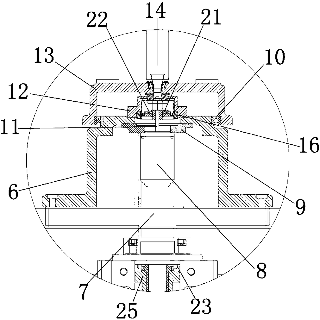
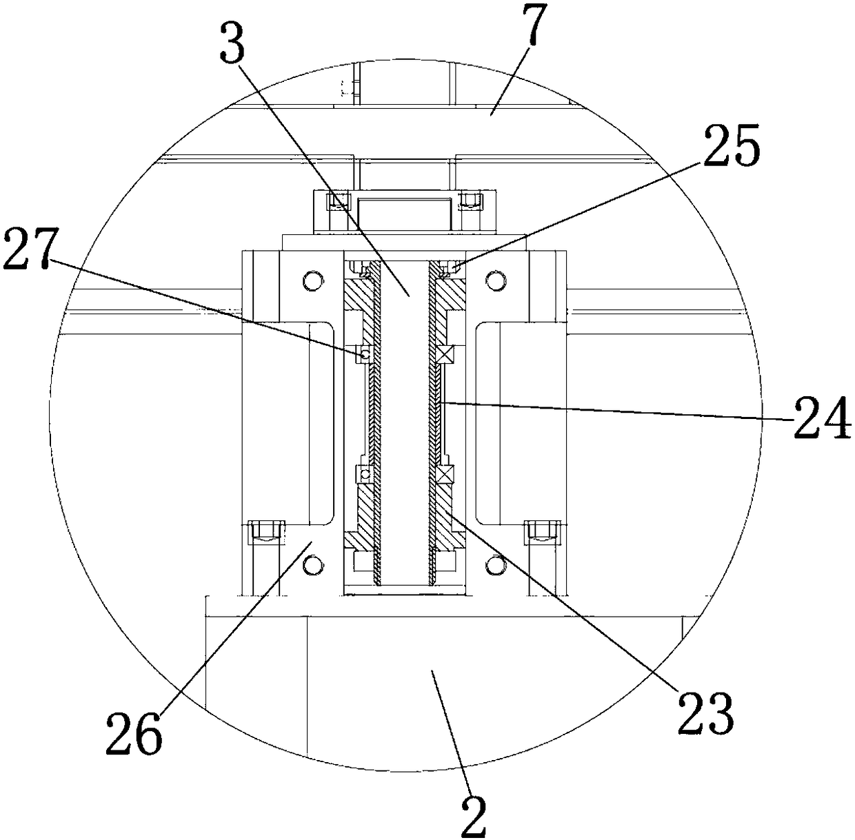
[0020] see Figure 1-3, the present invention provides a technical solution: a novel vertical bipolar reciprocating die-cutting machine, including a box body 1 for installing and fixing the first motor 4, and a horizontal plate 7 is installed on the inner wall of the box body 1 for installing Frame 2, the outer wall of horizontal plate 7 is connected with the inner wall of box body 1, and frame 2 is installed on the upper surface of box body 1 inner wall, is u...


PUM


Abstract

The invention discloses a novel vertical bipolar reciprocating die cutting machine. The machine comprises a box; a transverse plate is mounted on the inner wall of the box; the outer wall of the transverse plate is connected with the inner wall of the box; a frame is mounted on the upper surface of the inner wall of the box; a first motor is arranged on the left side of the frame; and the outer wall of the right side of the first motor is connected with the inner wall of the frame. In the novel vertical bipolar reciprocating die cutting machine, through cooperation of the first motor, a rotating rod and a rotating shaft, under the effect of a rotating frame, the first motor is an alternating-current servo motor, and the rotating speed of the motor is controlled through control of power generated by current passing through the motor to control the speed of a cutter cutting machined parts, so that the product quality of the novel vertical bipolar reciprocating die cutting machine is improved, the purchase cost of users is saved, the resource waste of the novel vertical bipolar reciprocating die cutting machine is prevented, and the novel vertical bipolar reciprocating die cutting machine is suitable for popularization and application.

Description

technical field [0001] The invention relates to the technical field of die-cutting machines, in particular to a novel vertical bipolar reciprocating die-cutting machine. Background technique [0002] The die-cutting machine is suitable for materials such as self-adhesive materials, protective films, electronic shielding materials, copper and aluminum foil, PVC film mylar paper, double-sided adhesive tape or foam cotton, and LCD reflectors, diffusers, buffers, and brightness enhancement in the optoelectronic industry. Film or silicone tape and other materials for die-cutting and molding equipment. The die-cutting process is the most commonly used process for packaging printed matter. It is to use a die-cutter to form a die-cutting plate according to the pattern required by the product design. Under the action of pressure, The forming process of rolling printed matter or other coiled blanks into desired shapes or cuts. The indentation process is to use a creasing knife or a c...

Claims


Application Information

Patent Timeline
Patent Type & Authority Applications(China)
IPC IPC(8): B26F1/38B26D5/08B26D5/06B26D7/06B26D7/00
CPCB26F1/38B26D5/06B26D5/086B26D7/00B26D7/0616
Inventor 张二琴
Owner 安吉腾新印刷厂
Why Eureka
Try Eureka