
Support hoisting mechanism and hoisting system

A technology for hoisting and supporting components, which is applied in the direction of erecting/assembling bridges, cranes, bridges, etc., which can solve problems such as narrow distances, damage to steel beams, and inadvisability, and achieve the effect of convenient use and simple structure

Pending Publication Date: 2018-07-10
NO 2 ENG CO LTD OF CHINA RAILWAY CONSTR 11 BUREAU GRP +1
View PDF9 Cites 2 Cited by
  • Summary
  • Abstract
  • Description
  • Claims
  • Application Information

AI Technical Summary

Problems solved by technology

[0002] At present, in the splicing construction of cast-in-situ concrete beams and steel box girders in urban overpasses, highways and railways, the design mode of steel beam brackets processed on the top of steel pipe columns is increasingly used, but the assembly is easy, and it is often difficult to start when removing the brackets, because the concrete beams are now After pouring or splicing of steel beams, the distance between the bottom and the top of the I-shaped steel beams is usually not more than 30cm (about 15-20cm for formwork and distribution beam square wood, etc., and the discharge amount of sand barrel is 10cm)
The crane cannot be hooked in such a narrow height space. Forced pulling will cause the load-bearing steel beam to fall and be damaged, as well as damage the crane itself and other facilities below.
It is precisely because the upper building and structure limit the further extension of the boom of the crane, so it is not advisable to use the crane directly.
[0003] Someone in the construction market has designed a modified lifting and unloading crane based on the method of lifting wood by humans. However, the distance between some supports is narrow, and this kind of crane cannot enter the work area, which is helpless; Leave a small hole for the support to be removed. After completion, use the fine-rolled threaded steel bar and the jack to cooperate with the removal. This method is of course the best, but many steel box girders are not allowed to leave holes, so some people weld temporarily at the bottom of the steel box girder. Hooks are lowered with steel ropes or inverted chains, but this method is sometimes not approved by the owner and the supervisor, and it is considered harmful to the steel beams

Method used


Image

  • Support hoisting mechanism and hoisting system
  • Support hoisting mechanism and hoisting system
  • Support hoisting mechanism and hoisting system

Examples


Embodiment

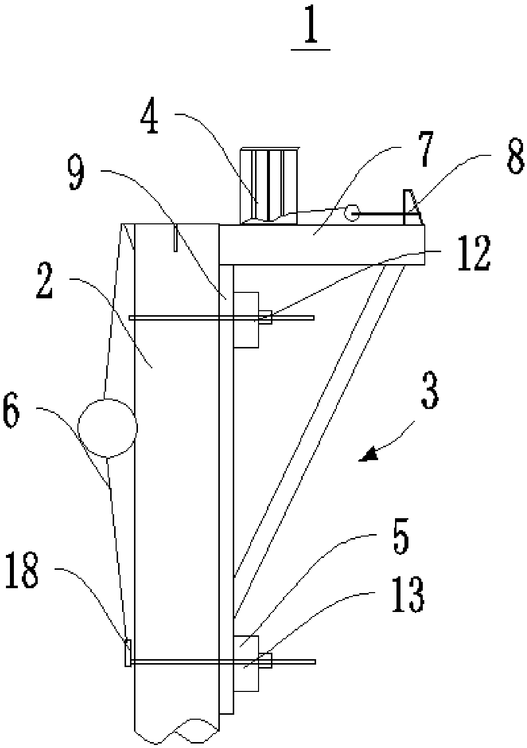
[0033] This embodiment provides a hoisting system, which includes a bracket hoisting mechanism 1 .

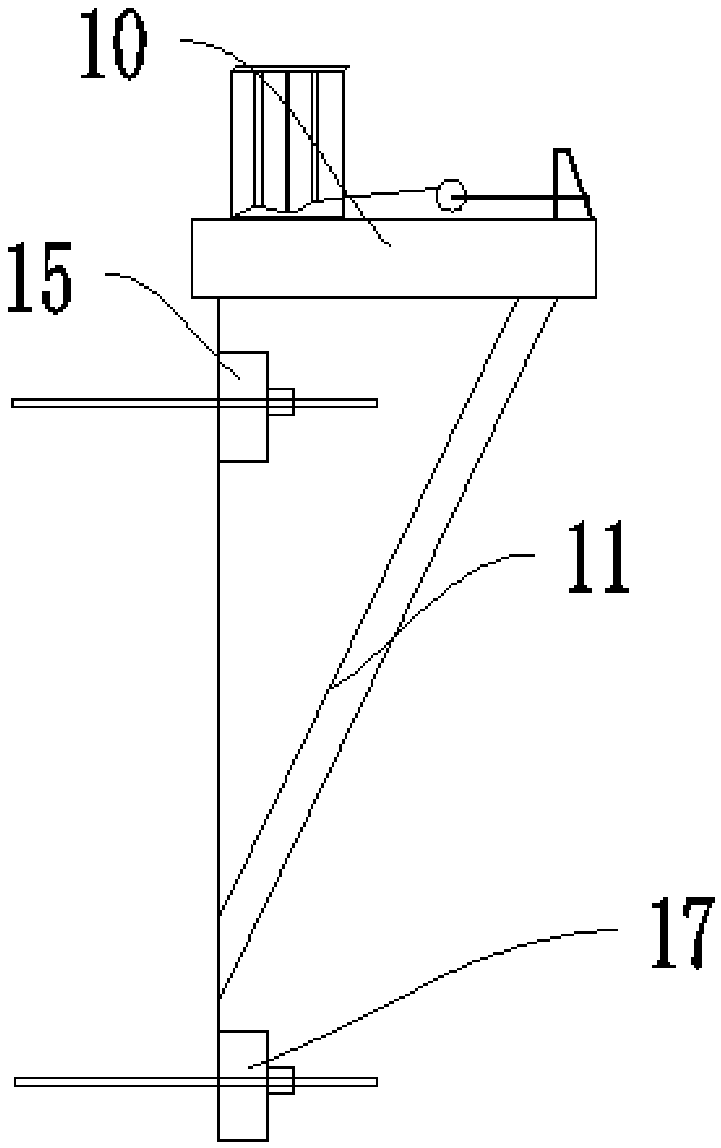
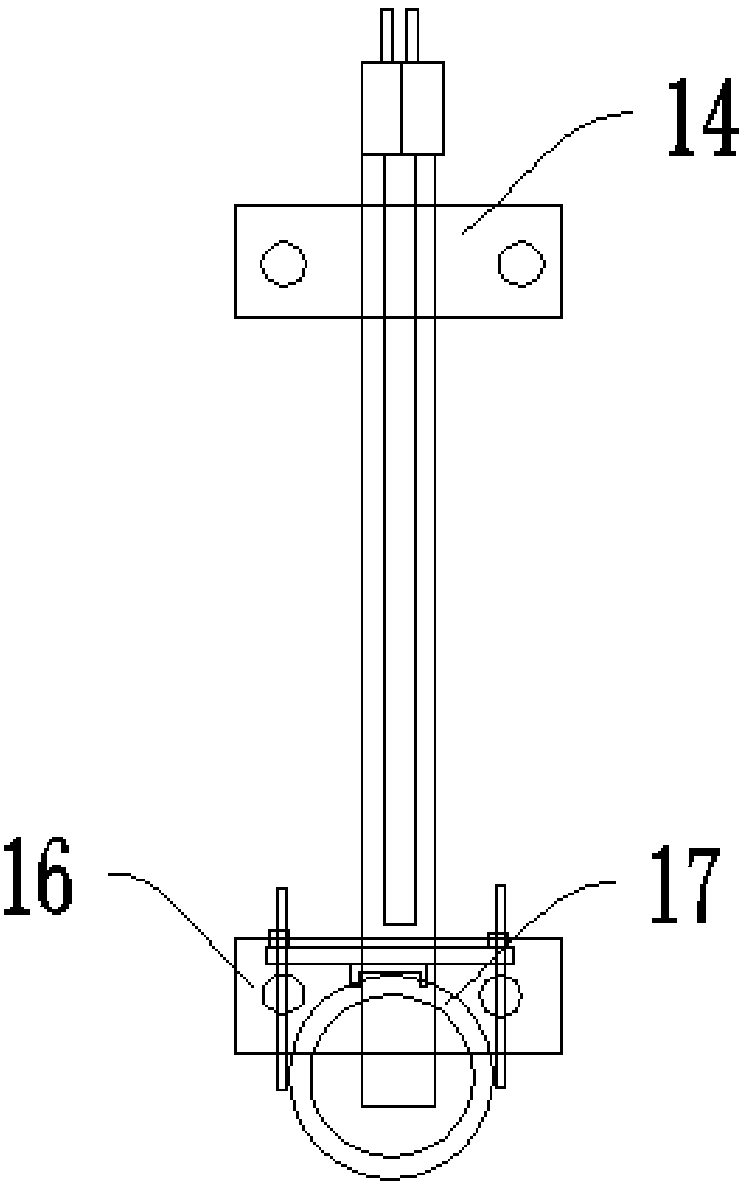
[0034] see Figure 1 to Figure 4 The bracket hoisting mechanism 1 includes a column 2, a hoisting assembly 3 and an I-beam 4, the hoisting assembly 3 includes a connecting member 5, an inverted chain 6, a support member 7 and a tensioner 8; the I-beam 4 is movably arranged on the column 2 Above; the support member 7 is movably installed on the column 2 through the connecting member, the upright chain 6 is installed on one side of the upright 2 , the upside down chain 6 is connected with the support member 7 in transmission, and the uplink 6 can drive the support member 7 along the upright column 2 The tension device 8 is installed on the support member 7, and the tension device 8 is connected with the I-beam 4 in transmission, and the tension device 8 can pull the I-beam 4 to the support member 7.

[0035] Further, in this embodiment, the support member 7 includes a buttress c...


PUM


Abstract

The invention provides a support hoisting mechanism and a hoisting system, and belongs to the technical field of construction machines. The support hoisting mechanism comprises a stand column, a hoisting assembly and an H steel beam. The hoisting assembly comprises a connecting component, a chain block, a supporting component and a tensioner. The H steel beam is movably arranged on the stand column. The supporting component is movably installed on the stand column through the connecting component. The chain block is installed on one side of the stand column and is further in drive connection with the supporting component. The chain block can drive the supporting component to move in the length direction of the stand column. The tensioner is installed on the supporting component and is further in drive connection with the H steel beam. The tensioner can pull the H steel beam onto the supporting component. By adoption of the hoisting system, the dropping speed and space height of rod pieces can be effectively controlled, and the space meeting the normal operation requirement of a crane is provided.

Description

technical field [0001] The invention relates to the technical field of construction machinery, in particular to a bracket hoisting mechanism and a hoisting system. Background technique [0002] At present, in the splicing construction of cast-in-situ concrete beams and steel box girders in urban overpasses, highways and railways, the design mode of steel beam brackets processed on the top of steel pipe columns is increasingly used, but the assembly is easy, and it is often difficult to start when removing the brackets, because the concrete beams are now After pouring or splicing of steel beams is completed, the distance between the bottom and the top of the I-beams is often no more than 30cm (about 15-20cm for formwork and distribution beams, and 10cm for the sand barrel). The crane cannot be hooked in such a narrow height space. Forced pulling will cause the load-bearing steel beam to fall and be damaged, as well as damage the crane itself and other facilities below. . It...

Claims


Application Information

Patent Timeline
IPC IPC(8): B66C23/20B66C23/62E01D21/00
CPCE01D21/00B66C23/203B66C23/208B66C23/62
Inventor 邹永泉郭昭赢凌俊东赵凯兵陶利范亚峰
Owner NO 2 ENG CO LTD OF CHINA RAILWAY CONSTR 11 BUREAU GRP
Learn More