
Prefabricated-slab connecting structure

A technology of prefabricated panels and structures, applied to building structures, floor slabs, building components, etc., can solve the problems of low industrialization, increased component cost, failure of industrialized production of electromechanical facilities, etc., to achieve fully automated production, reduce Formwork costs, the effect of improving site construction efficiency

Pending Publication Date: 2018-07-10
EAST CHINA ARCHITECTURAL DESIGN & RES INST
View PDF0 Cites 5 Cited by
  • Summary
  • Abstract
  • Description
  • Claims
  • Application Information

AI Technical Summary

Problems solved by technology

However, the volume of prefabricated concrete in the laminated slab accounts for less than 50% of the total volume of the floor slab, and it is still necessary to bind the upper reinforcement and pour concrete at the construction site. Compared with prefabricated beams, columns and other components, the degree of industrialization is not high; laminated slabs The use of mid-truss bars increases the cost of components; electromechanical pipelines still need to be laid on site, and electromechanical facilities have not been industrialized

Method used


Image

  • Prefabricated-slab connecting structure
  • Prefabricated-slab connecting structure
  • Prefabricated-slab connecting structure

Examples


Embodiment Construction

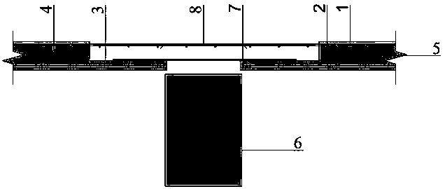
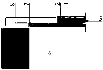
[0020] In order to better understand the above technical solutions of the present invention, a further detailed description will be given below in conjunction with the drawings and embodiments. The shaded parts in all the figures are prefabricated areas, and the blank parts between components are cast-in-place concrete areas.

[0021] Such as figure 1 and figure 2 As shown, the laminated panels are supported on laminated beams. The composite slab is composed of the slab prefabricated part 5 and the slab cast-in-place part; the composite beam is composed of the beam prefabricated part 6 and the beam cast-in-place part; The cast-in-place part is located in the connection area between the laminated beam and the laminated slab; the shape of the slab prefabricated part 5 is a stepped shape with a protruding middle and sinking around, that is, the slab prefabricated part 5 is composed of the middle part and the surrounding protruding part, similar to the Each perimeter of the sl...


PUM


Abstract

The invention relates to a prefabricated-slab connecting structure, and belongs to the field of prefabricated components in constructional engineering. According to the connecting structure between composite slabs, the composite slabs are composed of slab prefabricated parts and slab cast-in-place parts; the slab cast-in-place parts are located at connecting areas between the composite slabs; theslab prefabricated parts are each in a step shape with the middle being protruding and the periphery being sunken; upper layer steel bars of the slab prefabricated parts extend out of the middle protruding areas of the slab prefabricated parts, and lower layer steel bars of the slab prefabricated parts do not extend out of the periphery sunken areas of the slab prefabricated parts; additional lower layer steel bars are arranged on the lower layers of the slab cast-in-place parts, and the additional lower layer steel bars and the lower layer steel bars are indirectly connected in an overlappedmode; and steel bar meshes are laid on the upper layers of the slab cast-in-place parts, and the steel bar meshes and the upper layer steel bars are connected in an overlapped mode. Similarly, the prefabricated-slab connecting structure can also be used for connecting between the composite slabs and composite beams as well as between the composite slabs and a wall. According to the prefabricated-slab connecting structure, the prefabrication rate is increased, the manufacturing cost is low, the stiffness is large, and the formwork removing and hoisting requirements can be met.

Description

technical field [0001] The invention relates to the field of construction engineering, in particular to a structural configuration of a prefabricated component. Background technique [0002] The prefabricated construction method has brought about a significant increase in production efficiency. At present, my country is committed to the research and development of construction industrialization. Building industrialization can improve construction efficiency, improve building quality, low-carbon and energy-saving, and is in line with sustainable development. It is an effective way to transform the development mode of buildings. [0003] At present, the commonly used floor form in my country's prefabricated concrete structure is truss-reinforced laminated floor. The laminated floor has the advantages of good integrity, flat lower surface, and can save construction formwork. However, the volume of prefabricated concrete in the composite slab accounts for less than 50% of the t...

Claims


Application Information

Patent Timeline
IPC IPC(8): E04B1/16E04B5/17
CPCE04B1/161E04B5/17
Inventor 雷杰蔡磊花炳灿
Owner EAST CHINA ARCHITECTURAL DESIGN & RES INST
Learn More