Electric neutrality control method of MEMS electro-spray thrusters

A control method and thruster technology, applied in electrical components, accelerators, etc., to achieve the effects of wide applicability, avoidance of charge accumulation, and flexible and diverse combinations

Inactive Publication Date: 2018-07-10
BEIJING INST OF CONTROL ENG
View PDF5 Cites 0 Cited by
  • Summary
  • Abstract
  • Description
  • Claims
  • Application Information

AI Technical Summary

Problems solved by technology

[0006] In order to overcome the deficiencies in the prior art, the present invention provides a MEMS electrospray thruster electrical neutrality control method, which solves the problem of electrical neutrality control in the application process of the MEMS electrospray thruster array, and at the same time solves the problem of the MEMS electrospray thruster. Problems of thrust continuity and uniformity in array application

Method used


Image

  • Electric neutrality control method of MEMS electro-spray thrusters
  • Electric neutrality control method of MEMS electro-spray thrusters
  • Electric neutrality control method of MEMS electro-spray thrusters

Examples


Embodiment 1

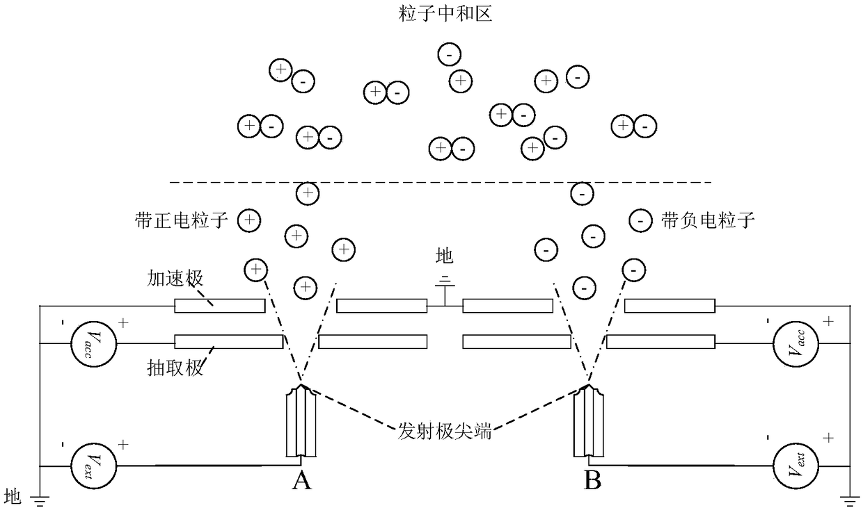
[0031] In this implementation, two thrusters are used to neutralize each other, the first thruster sprays positively charged particles, and the second thruster uses an extraction voltage of opposite polarity (V ext ) and accelerating voltage (V acc ) to cause it to spray negatively charged particles. Positively charged particles and negatively charged particles will be electrically neutralized in the neutralization zone. The first thruster and the second thruster are placed side by side, the acceleration plates of the first thruster and the second thruster are connected and common grounded, and the extraction plate and the emitter of the first thruster are connected to the extraction voltage source (the extraction voltage between the two electrodes for V ext ), the extraction plate and the accelerating plate are connected to the accelerating voltage source (the accelerating voltage between the two electrodes is V acc ); the extraction plate and emitter of the second thruste...

Embodiment 2

[0033] In this implementation, four thrusters are used to neutralize each other, and the four thrusters are arranged on a common ground. The first and fourth thrusters spray positively charged particles, and the second and third thrusters use oppositely polarized extraction voltages (V ext ) and accelerating voltage (V acc ) to make it spray negatively charged particles, and periodically change the polarity of the sprayed particles. Positively charged particles and negatively charged particles will be electrically neutralized in the neutralization zone. The first thruster and the second thruster are placed side by side in a horizontal direction, and the acceleration plate, the extraction plate and the emitter plate are respectively connected to each other in a horizontal direction. The first thruster and the third thruster are placed side by side vertically, and the acceleration plate, the extractor plate and the emitter plate are vertically corresponding to adjacent connecti...

Embodiment 3

[0036] In this implementation, eight thrusters are used to neutralize each other, and the eight thrusters are set up on the same ground. The first, third, sixth, and eighth thrusters spray positively charged particles, and the second, fourth, fifth, and seventh thrusters use opposite polarities. The extraction voltage (V ext ) and accelerating voltage (V acc) to cause it to spray negatively charged particles. Positively charged particles and negatively charged particles will be electrically neutralized in the neutralization zone. The first thruster, the second thruster, and the third thruster are arranged horizontally in sequence, and the accelerating plate, the extracting plate and the emitter plate are sequentially and correspondingly connected adjacently. The first thruster, the fourth thruster, and the sixth thruster are vertically arranged in sequence, and the acceleration plate, extraction plate and emitter plate are vertically connected to each other in sequence. The...


PUM


Abstract

The invention provides an electric neutrality control method of MEMS electro-spray thrusters. Thrusters with different charges work pairwise and are arranged and combined to neutralize the plume, thethruster is kept electrically neutral overall, and charge accumulation is avoided. The control method is easy to realize and flexible in manner, no extra equipment is introduced, and the satellite weight is not increased. The electrode voltage polarity of the same thruster is changed regularly so that the thruster sprays positive or negative electric particles alternatively, two paired thrusters spary the particles or liquid drops with opposite charges, and the thrust of the two thrusters is kept continuous and uniform.

Description

technical field [0001] The invention belongs to the application field of electrospray thrusters and relates to a method for controlling the electrical neutrality of MEMS electrospray thruster arrays. Background technique [0002] MEMS electrospray thrusters are currently one of the research hotspots in the field of micro-nano satellite propulsion. During the working process of the MEMS electrospray thruster array, the propellant (ionic liquid) ejects charged particles or droplets outward under the coupling effect of multi-physics fields such as electric field force and surface tension, thereby generating thrust. But with the accumulation of time, a single injection of positively charged particles or negatively charged particles will cause the thruster to accumulate charges, making the entire star charged with full or negative charges, which will have an adverse effect on the normal operation of the thruster and even the safety of the star. [0003] For the working principle...

Claims


Application Information

Patent Timeline
Patent Type & Authority Applications(China)
IPC IPC(8): H05H15/00
Inventor 耿金越龙军刘旭辉沈岩
Owner BEIJING INST OF CONTROL ENG
Why Eureka
Try Eureka