Multi-surface integrated processing center

A machining center and integrated technology, applied in the direction of metal processing equipment, metal processing machinery parts, manufacturing tools, etc., to achieve the effects of saving equipment costs, reducing precision error problems, and reducing moving distances

Pending Publication Date: 2018-07-13
宁波江北百吉机械有限公司
View PDF5 Cites 8 Cited by
  • Summary
  • Abstract
  • Description
  • Claims
  • Application Information

AI Technical Summary

Problems solved by technology

However, in the prior art, there is no vertical and horizontal dual-spindle machining center with a single column and a composite spindle.

Method used


Image

  • Multi-surface integrated processing center
  • Multi-surface integrated processing center
  • Multi-surface integrated processing center

Examples


Embodiment 1

[0029] In the first embodiment, the X-axis slide rail and its screw drive system are arranged on the Y-axis slide rail and the screw drive system. According to the size and shape of the base and the different operating habits, the two can be set interchangeably.

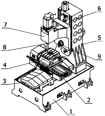
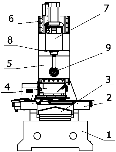
[0030] A column is also arranged on the base, and a Z-axis guide rail and a Z-axis screw drive system are arranged on the column, and a servo motor driving the Z-axis direction is arranged on the top of the column. The Z-axis guide rail is provided with a spindle mounting frame. In Embodiment 1, the spindle mounting frame is an F-shaped structure, including a horizontal extension and a vertical extension at the top, and the middle part of the spindle mounting frame is a Z-axis screw pair.

[0031] The vertical spindle is arranged on the top of the horizontal extension of the spindle mounting seat, and the vertical spindle is arranged vertically downward. The structure is similar to a standard vertical machining cent...

Embodiment 2

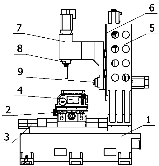
[0035] Embodiment 2 is an improved solution of Embodiment 1. Its bed, X-axis guide rail, Y-axis guide rail, and rotary table are all the same as Embodiment 1, and it is also a solution using a single column and a set of Z-axis guide rails. Its difference lies in: its main shaft mounting frame only has the horizontal extension part, and no vertical extension part is provided, and the vertical main shaft and the horizontal machining main shaft are all arranged on the top of the horizontal extension part. The two are integrated on the top of the horizontal extension of the spindle mounting frame in a mutually perpendicular manner.

[0036] Embodiment 2 is exactly the same as Embodiment 1 when the vertical spindle is working. When the horizontal spindle is working, the Z axis and the Y axis are used as the processing surface, and the X axis is used as the feed direction for horizontal processing.

[0037] In Embodiment 1 and Embodiment 2, when the vertical machining center and the...


PUM


Abstract

The invention discloses a multi-surface integrated processing center. The multi-surface integrated processing center is characterized by only comprising a stand column, wherein a set of Z-axis motionmechanisms is utilized to drive a main shaft mounting frame; a vertical type main shaft and a horizontal type main shaft are simultaneously integrated on a main shaft mounting table; the vertical typemain shaft is mounted on a horizontal extending part of the main shaft mounting frame; the horizontal type main shaft is mounted on a vertical extending part; or the horizontal type main shaft and the vertical type main shaft are integrated on the horizontal extending part. A workpiece is mounted on a workbench which rotates by 360 degrees, and the rotary workbench is additionally arranged on a rail of an axis X and a rail of an axis Y. The multi-surface integrated processing center can complete processing processes for the top surface and four side surfaces of the workpiece once, does not need to re-clamp the workpiece halfway, reduces replacement time, and solves the problem that precision is reduced as the workpiece is clamped by many times. According to the multi-surface integrated processing center disclosed by the invention, one stand column and one set of Z-axis lifting mechanisms are adopted, so that equipment cost is reduced, programming simplification is facilitated, and programming workload of an operator is reduced.

Description

technical field [0001] The invention relates to a machining center, in particular to a multi-surface integrated machining center combining vertical and horizontal machining centers. Background technique [0002] Machining centers are also called CNC (Computer Numerical Control) milling machines. Machining centers are divided into vertical machining centers and horizontal machining centers according to the relative position of the spindle and the worktable. Taking the standard six-sided cube workpiece as an example, the spindle of the vertical machining center is used to process the top surface of the workpiece from top to bottom, and the horizontal machining center is used to process the side of the workpiece. When the horizontal machining center cooperates with After the rotary table, all four sides of the workpiece can be machined. [0003] When the workpiece is clamped to the machining center, all positioning references need to be calibrated, and there are certain error...

Claims


Application Information

Patent Timeline
Patent Type & Authority Applications(China)
IPC IPC(8): B23Q1/01B23Q5/36B23Q5/40
CPCB23Q1/015B23Q1/017B23Q5/36B23Q5/40
Inventor 杨依李倍豪
Owner 宁波江北百吉机械有限公司
Why Eureka
Try Eureka