Eureka AIR delivers breakthrough ideas for toughest innovation challenges, trusted by R&D personnel around the world.

Ceramic slurry jetting forming device

A molding device and spraying technology, which is applied in the field of ceramic processing, can solve problems such as high cost, slow production speed, and complicated operation, and achieve the effects of improving efficiency, saving materials, and reducing the rate of defective products

Inactive Publication Date: 2018-07-13
许光权
View PDF5 Cites 11 Cited by
  • Summary
  • Abstract
  • Description
  • Claims
  • Application Information

AI Technical Summary

Problems solved by technology

However, the operation of this grouting molding process is complicated and requires manual operation, the production speed is slow and the cost is high

Method used


Image

  • Ceramic slurry jetting forming device
  • Ceramic slurry jetting forming device
  • Ceramic slurry jetting forming device

Examples


Embodiment Construction

[0021] In order to make the object, technical solution and advantages of the present invention clearer, the present invention will be further described in detail below in conjunction with the accompanying drawings and embodiments. It should be understood that the specific embodiments described here are only used to explain the present invention, not to limit the present invention.

[0022] Unless the context clearly states otherwise, the number of elements and components in the present invention can exist in a single form or in multiple forms, and the present invention is not limited thereto.

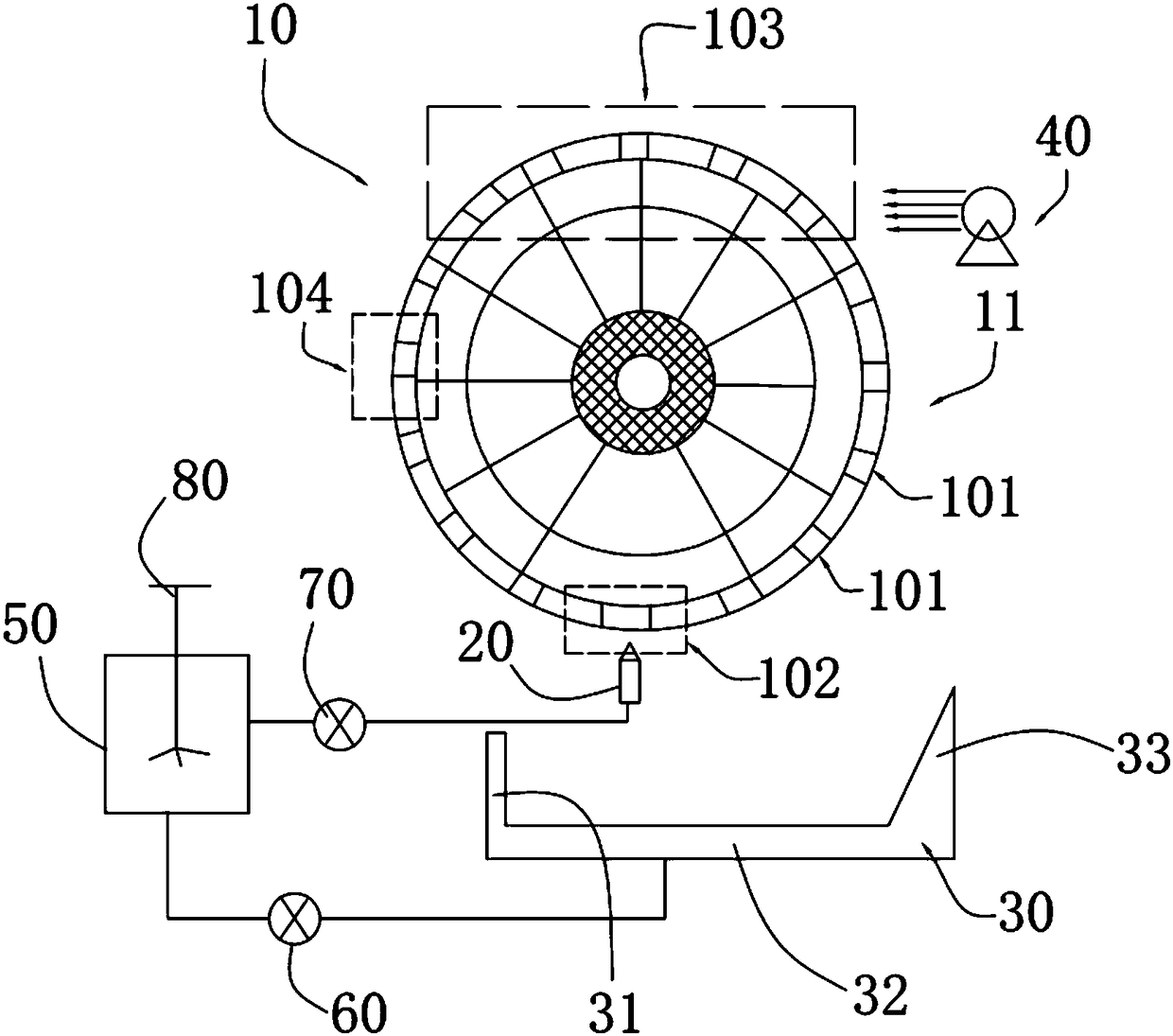
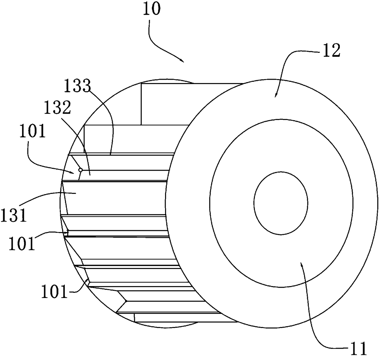
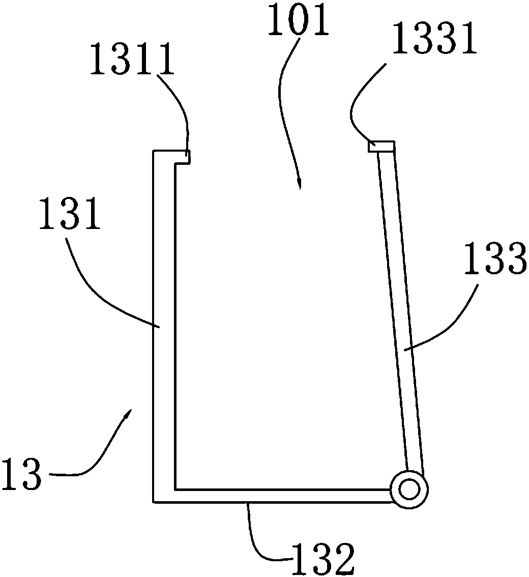
[0023] Please also see Figure 1-3 , the ceramic spray molding device provided by the present invention comprises the rotary part 10 that is used to fix a plurality of moulds, the multiple nozzles 20 that are used to inject slurry, the slurry recovery groove 30 that is used to reclaim slurry, and is used for mould. A plurality of blowers 40 for drying the inner body.

[0024] For the ...


PUM


Abstract

The invention provides a ceramic slurry jetting forming device. The ceramic slurry jetting forming device comprises a rotating component used for fixing multiple molds, and multiple nozzles used for slurry jetting; the multiple molds rotate along with the rotating component, and when slurry jetting openings of the molds right face the nozzles, the nozzles jet the slurry into the molds to form blank bodies. According to the ceramic slurry jetting forming device, the nozzles are used for jetting the slurry into the slurry jetting openings of the molds, the blank bodies are formed in the molds, the structure is simple, automatic control is easy, production efficiency can be improved, and manual cost is reduced.

Description

technical field [0001] The invention belongs to the field of ceramic processing, and in particular relates to a ceramic spraying molding device. Background technique [0002] At present, ceramic products with a circular cross section are usually processed by an extrusion molding process; however, ceramic products with a non-circular cross section can only be processed by a slip casting process. [0003] For the slip casting process, the conventional practice is to inject the slurry into the mold of the ceramic product, and then drain the water in the slurry to obtain a green body attached to the mold. However, the operation of this grouting molding process is complicated and requires manual operation, and the production speed is slow and the cost is high. Contents of the invention [0004] The purpose of the present invention is to provide a ceramic spray molding device. [0005] The technical solution of the present invention is as follows: a ceramic spray molding devic...

Claims


Application Information

Patent Timeline
Patent Type & Authority Applications(China)
IPC IPC(8): B28B1/26B28B11/24B28B17/00B28C3/00
CPCB28B1/26B28B1/261B28B1/267B28B11/243B28B17/00B28C3/00
Inventor 许光权
Owner 许光权
Why Eureka
Eureka Blog
Learn More