Steel pipe fixing and cutting device

A cutting device and steel pipe technology, applied in the direction of pipe shearing device, shearing device, accessory device of shearing machine, etc., can solve the problems of reducing the service life of the cutting device, hindering the cutting work of the cutting device, and reducing the cutting efficiency, etc., so as to improve the recycling rate. Efficiency, improve cutting efficiency, simple structure effect

Inactive Publication Date: 2018-07-17
宁波鑫神泽汽车零部件有限公司
View PDF6 Cites 13 Cited by
  • Summary
  • Abstract
  • Description
  • Claims
  • Application Information

AI Technical Summary

Problems solved by technology

Before cutting the steel pipe, the steel pipe needs to be fixed to prevent the steel pipe from shifting. Most of the existing steel pipe cutting devices require the user to manually clamp and fix the steel pipe, which has poor fixing effect and low safety factor; in addition, the existing The steel pipe cutting device will generate high temperature due to friction when cutting the steel pipe, which will promote the weakness of the cutting device and reduce the service life of the cutting device
At the same time, debris and slag generated during cutting will continue to accumulate in the cutting gap of the steel pipe, which will hinder the cutting work of the cutting device and reduce the cutting efficiency

Method used


Image

  • Steel pipe fixing and cutting device
  • Steel pipe fixing and cutting device

Examples


Embodiment Construction

[0019] Further detailed explanation through specific implementation mode below:

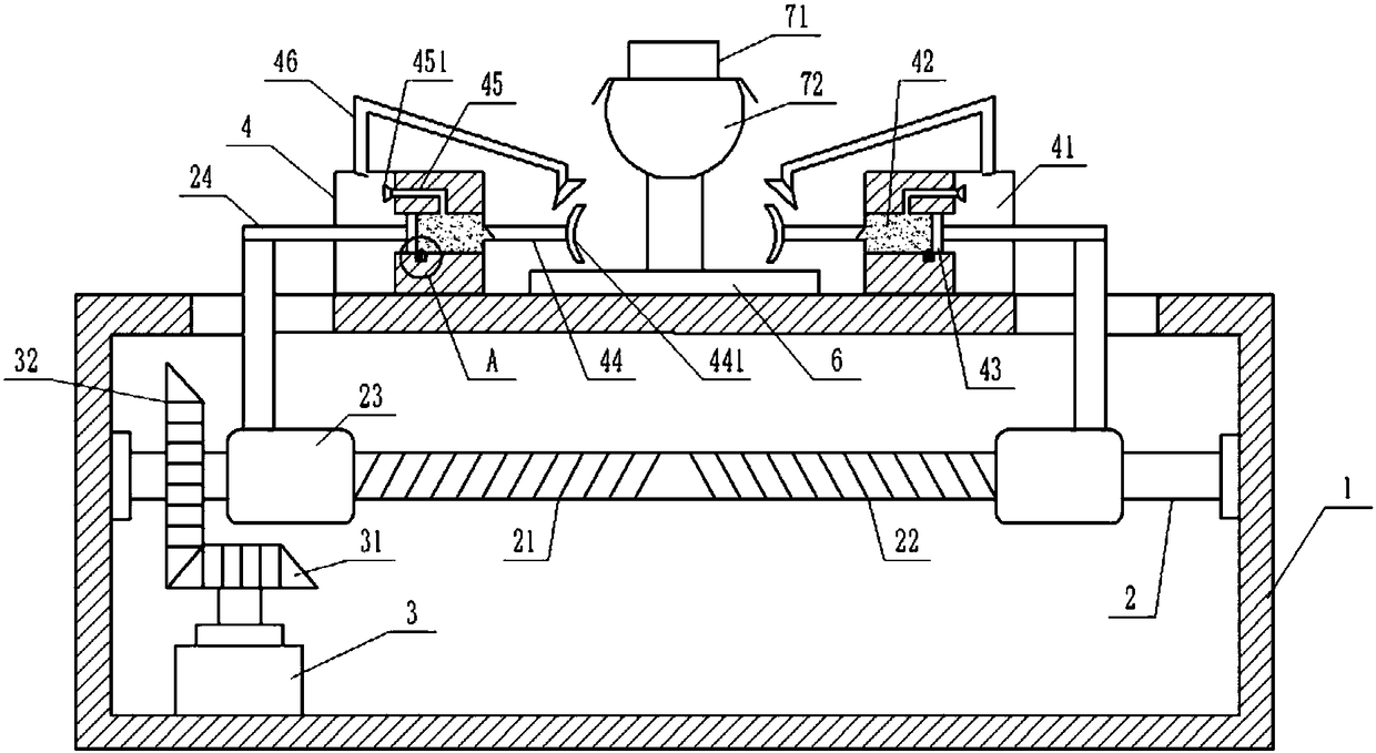
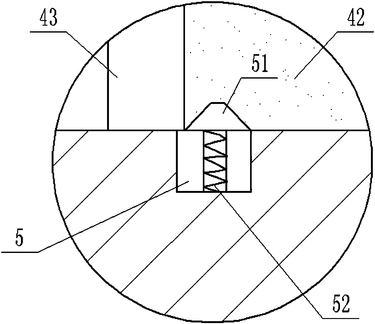
[0020] The reference signs in the drawings of the description include: support frame 1, threaded rod 2, forward thread 21, reverse thread 22, threaded pipe 23, connecting rod 24, motor 3, first bevel gear 31, second bevel gear 32, sliding Box 4, slag collection chamber 41, liquid storage chamber 42, piston 43, fixed pipe 44, clamping piece 441, spray pipe 45, shower 451, slag suction pipe 46, groove 5, bump 51, spring 52, Steel pipe placement platform 6, cylinder 71, cutting tool 72.

[0021] The embodiment is basically as attached figure 1 And attached figure 2 Shown: a steel pipe fixed cutting device, including a cutting mechanism and a steel pipe fixing mechanism, the steel pipe fixing mechanism includes a support frame 1 and a sliding box 4, and the upper end of the support frame 1 is provided with a steel pipe placement platform 6. The cutting mechanism includes a cylinder 71, a cutting ...


PUM


Abstract

The invention relates to the technical field of steel pipe production and machining and particularly discloses a steel pipe fixing and cutting device. The steel pipe fixing and cutting device comprises a cutting mechanism and a steel pipe fixing mechanism, and the steel pipe fixing mechanism comprises a supporting frame, sliding boxes and a steel pipe storing table. The cutting mechanism is fixedly connected to the upper portion of the steel pipe storing table, and the sliding boxes are symmetrically distributed on the two sides of the steel pipe storing table. A threaded rod is fixedly connected into the supporting frame and connected with a power mechanism, and a right-hand thread and a left-hand thread are symmetrically arranged on the threaded rod. The surfaces of the right-hand threadand the left-hand thread are connected with threaded pipes correspondingly, and the threaded pipes are fixedly connected with connecting rods. The sliding boxes are slidably connected with the supporting frame and internally provided with residue collecting chambers, liquid storage cavities, pistons, fixing pipes, spraying pipes, residue suction pipes and position clamping mechanisms. According to the steel pipe fixing and cutting device, steel pipe fixing, cooling of the cutting mechanism and recovery of cut shred residues can be achieved without manual operation, the operation cost is low,and the steel pipe cutting efficiency is high.

Description

technical field [0001] The invention relates to the technical field of steel pipe production and processing, in particular to a steel pipe fixed cutting device. Background technique [0002] Steel pipes are not only used to transport fluids and powdery solids, but also to exchange heat and manufacture mechanical parts and containers. It is an economical steel. Steel pipes are widely used in the automobile industry, and are often used as automobile transmission shaft pipes, automobile muffler pipes, condensation pipes, automobile exhaust pipes, steering shaft pipes, automobile thrust pipes, automobile shock absorber oil storage, etc. When producing steel pipes for automobiles, it is necessary to use a steel pipe cutting device to cut the steel pipes into small sections of steel pipes that meet the size requirements. Before cutting the steel pipe, the steel pipe needs to be fixed to prevent the steel pipe from shifting. Most of the existing steel pipe cutting devices require ...

Claims


Application Information

Patent Timeline
Patent Type & Authority Applications(China)
IPC IPC(8): B23D33/02B23D21/00B23D33/00B23Q11/00B23Q11/10
CPCB23D33/02B23D21/00B23D33/00B23Q11/00B23Q11/0046B23Q11/10
Inventor 孙文清
Owner 宁波鑫神泽汽车零部件有限公司
Why Eureka
Try Eureka