Clamping and jacking device of aluminum electrolytic cell

A jacking device and aluminum electrolytic cell technology, applied in the field of aluminum electrolysis, can solve problems such as increased workload, easily damaged anodes, high pressure, etc., and achieve the effects of increased contact area, low operating cost, and reduced voltage

Active Publication Date: 2018-07-17
党星培
View PDF11 Cites 12 Cited by
  • Summary
  • Abstract
  • Description
  • Claims
  • Application Information

AI Technical Summary

Problems solved by technology

[0003] The present invention solves the problem that the wheel clamper applies too much pressure to the aluminum frame, easily damages the anode, and adding conductive fillers between the anode guide rod and the aluminum frame or at the lower end of the anode guide rod will increase the workload and operating costs. The problem is to provide a clamping and tightening device for aluminum electrolytic cells, so as to realize the reliable and stable clamping of the anode under the premise of ensuring the integrity of the aluminum frame and the anode, the anode lifting operation is highly mechanized and automated, and the anode is controlled The lifting operation precision is high, the contact voltage between the anode guide rod and the aluminum frame is reduced and the structure is simple, no arc is generated when the relative displacement between the anode guide rod and the aluminum frame occurs, and the purpose of the anode guide rod not moving in the left and right direction

Method used


Image

  • Clamping and jacking device of aluminum electrolytic cell
  • Clamping and jacking device of aluminum electrolytic cell
  • Clamping and jacking device of aluminum electrolytic cell

Examples


Embodiment 1

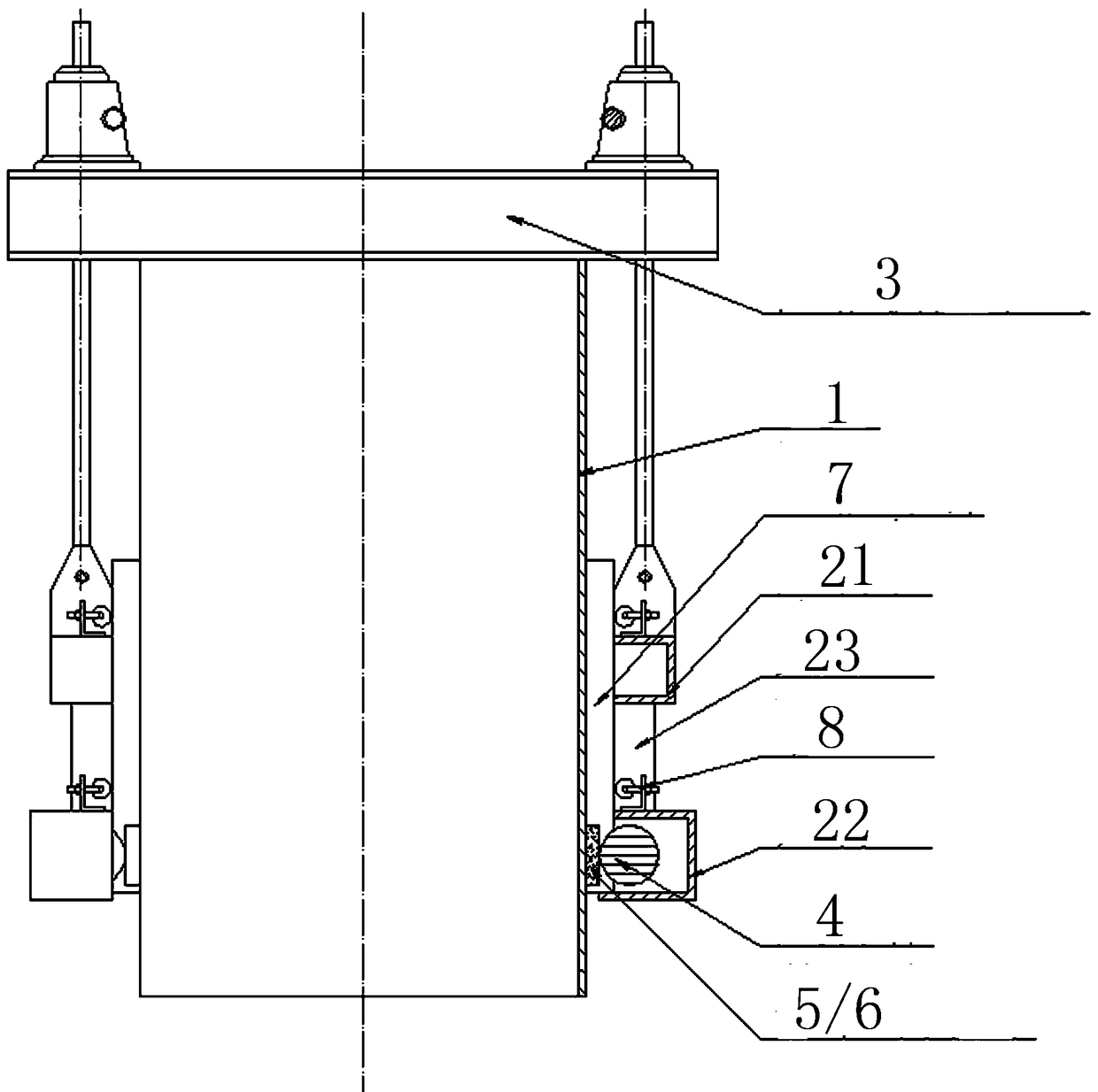
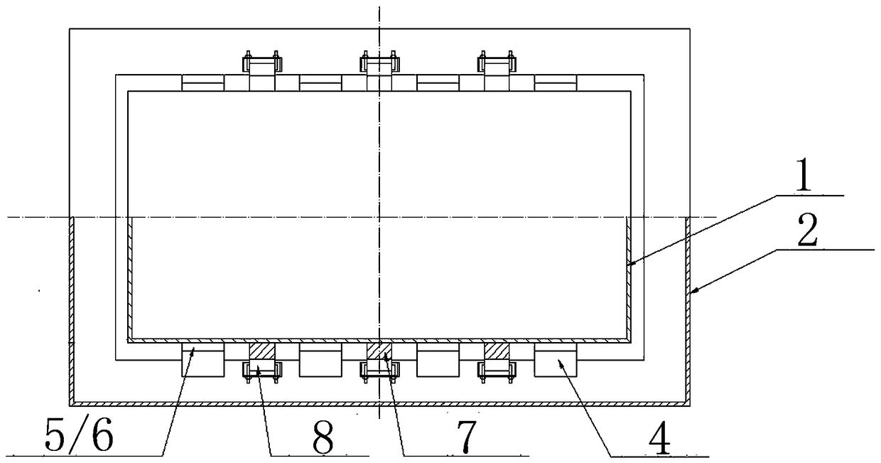
[0049] like figure 1 As shown, the clamping frame 2 is first set up around the aluminum frame 1 with several conductors, and then the clamping frame 2 is connected with the anode lifting mechanism 3. The clamping frame 2 is composed of upper and lower rows (the upper row of clamping frames 21 and the lower row of clamping frames 22), the upper and lower rows of clamping frames are connected by a support 23. Several clampers 4 are arranged in the clamping frame 22 of the lower row, and the clampers 4 are located between the aluminum frame 1 and the clamping frame 2 , and several hanging boards 5 or flexible chains 6 are arranged around the clampers 4 . Several anode guide rods 7 are set between the aluminum frame 1 and the upper and lower rows of clamping frames, and several jacking devices 8 are set between the anode guide rods 7 and the clamping frame 2, and the jacking devices 8 are located in the upper row and the lower row. top of row holder frame. like figure 2 As sh...

Embodiment 2

[0064] like figure 1 As shown, the clamping frame 2 is first arranged around the aluminum frame 1 with several conductors, and then the clamping frame 2 is connected with the anode lifting mechanism 3 . The clamping frame 2 is a row, and several clampers 4 are arranged in the clamping frame 2, and the clamper 4 is located between the aluminum frame 1 and the clamping frame 2, and several hanging plates 5 are arranged around the clamper 4 or flexible chain6. Several anode guide rods 7 are also arranged between the aluminum frame 1 and the clamping frame 2, and several clamping devices 8 are arranged between the anode guide rods 7 and the clamping frame 2, and the clamping devices 8 are located on the clamping frame 2 In the groove and on top of the clamping frame. like figure 2 As shown, the anode guide rod 7 is located between two adjacent holders.

[0065] The number of tensioners in contact with the anode guide rod 7, the position and size of the pressure exerted by th...

Embodiment 3

[0077] like Figure 10 As shown, an anode lifting mechanism 3 is also arranged around the clamping frame. The anode lifting mechanism 3 is located between the cell shell 10 and the superstructure 9 of the electrolytic cell, one end of which is connected to the cell shell, and the other end is connected to the superstructure. The holding frame is connected with the upper structure through the suspension rod 11. When the anode lifting mechanism is started, the upper structure of the electrolytic cell will be moved up and down, and the anode, hanging plate or flexible chain, clamping frame and clamper will be moved to the specified position synchronously, and the clamping frame will be adjusted to the specified position of the process. height range.

[0078] The anode lifting mechanism is a screw type lifting mechanism.


PUM


Abstract

The invention relates to the technical field of aluminum electrolysis, in particular to a clamping and jacking device of an aluminum electrolytic cell. The problems that the pressure intensity appliedby wheel type clamp holders to an aluminum frame is too large, an anode is prone to being damaged, and the workload and operation cost are increased by adding filler with conductivity are solved. According to the clamping and jacking device of the aluminum electrolytic cell, a clamping frame is arranged around an aluminum frame, wherein multiple conductors are arranged in the aluminum frame, andan anode lifting mechanism used for adjusting the clamping frame to ascend and descend is further included; multiple clamp holders are arranged between the aluminum frame and the clamping frame, and at least one clamping wheel is arranged on each clamp holder; multiple hanging plates or at least one flexible chain matched with each clamp holder and driven by the at least one clamping wheel on thecorresponding clamp holder is further included; and one part of at least one hanging plate or flexible chain is kept between the corresponding clamp holder and the aluminum frame. According to the clamping and jacking device, the aim of firmly and stably clamping the anode or enabling the anode to ascend and descend can be guaranteed on the premise that the aluminum frame and the anode are intact,the contact voltage between an anode guide rod and the aluminum frame is reduced, and the structure is simple.

Description

technical field [0001] The invention relates to the technical field of aluminum electrolysis, in particular to a clamping and tightening device for an aluminum electrolytic cell. Background technique [0002] The patent with the application number 201711220109.6 discloses a clamping frame for an aluminum electrolytic cell, in which several wheel clamps are arranged on the top or in the groove of the clamping frame, and the pressure clamp applied to the anode by the wheel clamps Hold and lift the anode, and rely on the kinetic force generated by the rotation of the wheel holder to drive the anode up and down, and lift the anode to the designated position. The clamping wheel in the wheel clamp is generally in linear contact with the aluminum frame. When the pressure exerted by the clamping wheel on the aluminum frame is constant, due to the small contact area between the clamping wheel and the aluminum frame, the pressure on the aluminum frame If it is too large, it will dama...

Claims


Application Information

Patent Timeline
IPC IPC(8): B66C1/16B66C13/08C25C3/12
CPCB66C1/16B66C13/08C25C3/12B66C1/447C25C3/10
Inventor 党星培
Owner 党星培
Why Eureka
Try Eureka