Water injection device of a combustion engine and method for operating same

A technology for water spray equipment and internal combustion engines, which is applied to mechanical equipment, internal combustion piston engines, combustion engines, etc., and can solve problems affecting the combustion characteristics of internal combustion engines, etc.

Inactive Publication Date: 2018-07-17
ROBERT BOSCH GMBH
View PDF7 Cites 4 Cited by
  • Summary
  • Abstract
  • Description
  • Claims
  • Application Information

AI Technical Summary

Problems solved by technology

However, these components affect the combustion characteristics of the internal combustion engine and require additional operating materials

Method used


Image

  • Water injection device of a combustion engine and method for operating same
  • Water injection device of a combustion engine and method for operating same
  • Water injection device of a combustion engine and method for operating same

Examples


Embodiment Construction

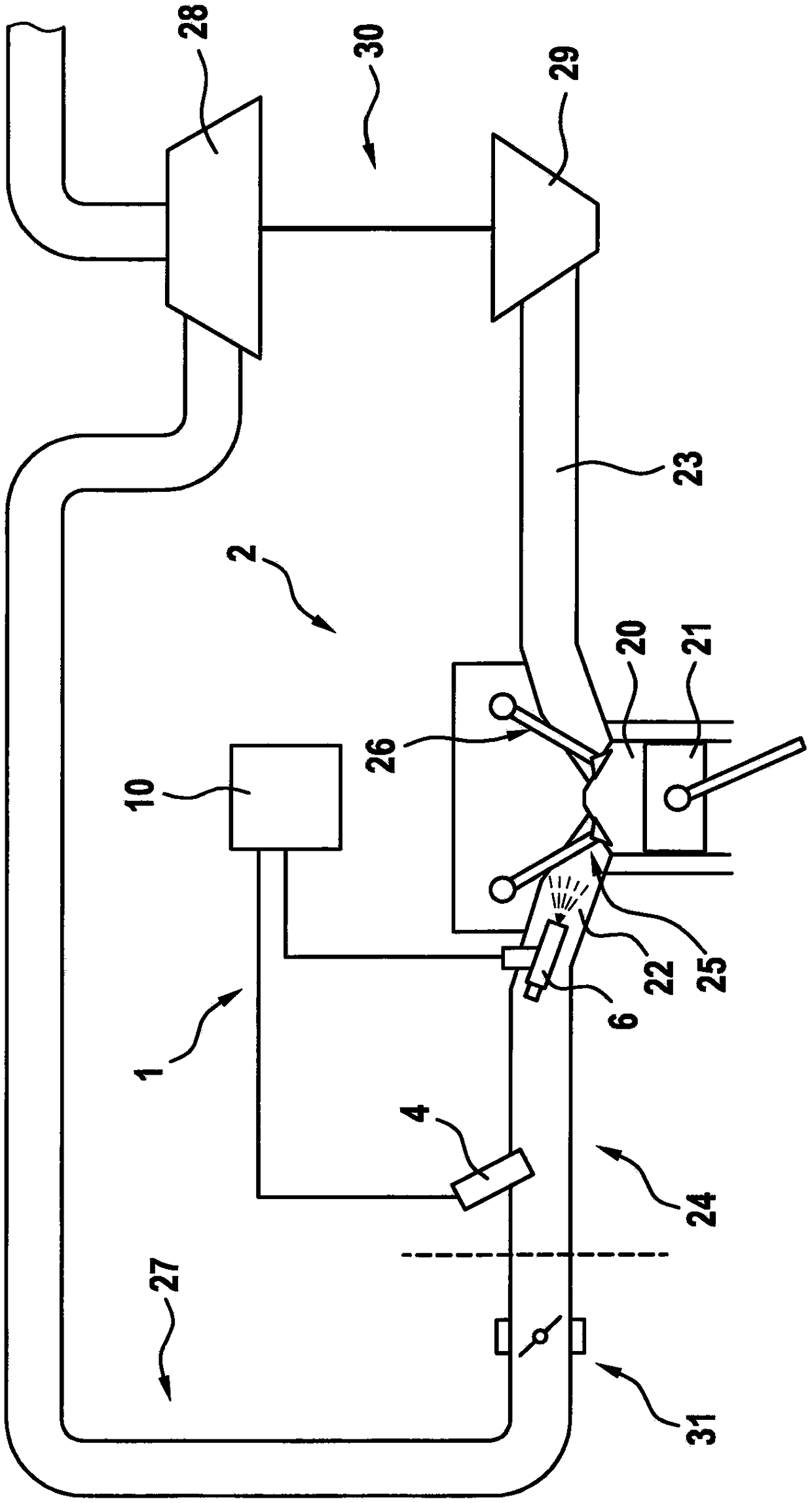
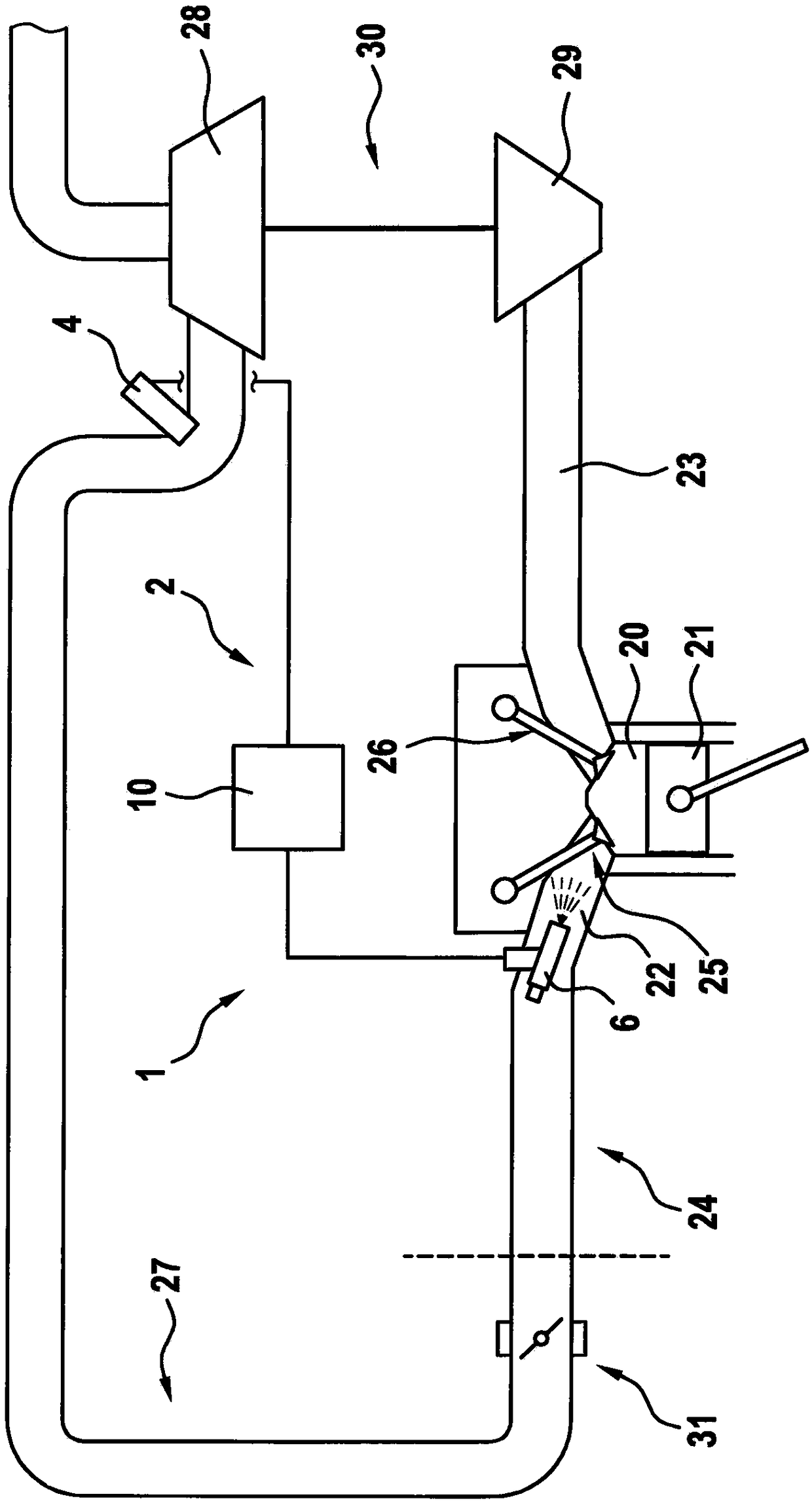
[0026] Refer below figure 1 and 2 The water injection device 1 of the internal combustion engine 2 according to the first embodiment will be described in detail. In particular, internal combustion engine 2 is operated according to the Otto principle with direct gasoline injection.

[0027] exist figure 1 An internal combustion engine 2 with a plurality of cylinders and a part of the inventive water injection system 1 are schematically shown in . The internal combustion engine 2 comprises a combustion chamber 20 per cylinder, in which a piston 21 can move back and forth. Furthermore, internal combustion engine 2 preferably has one intake duct 22 per cylinder, via which air is supplied to combustion chamber 20 . The exhaust gas is carried away via the exhaust gas channel 23 . For this purpose, an intake valve 25 is arranged on the intake duct 22 and an exhaust valve 26 is situated on the exhaust duct 23 .


PUM


Abstract

The invention relates to a water injection device. The water injection device comprises the components of a water tank for storing water; at least one water-fuel injector which is connected with the water tank by means of a water pipeline and can be supplied with fuel through a fuel pipeline, wherein the water-fuel injector is used for spraying water and/or fuel; and at least one water injecting device which is connected with the tank and is set for injecting water. The water injection device further comprises a conveying element which is used for conveying water from the water tank to the water injector and/or water-fuel injector and further comprises a control unit. The control unit is set for opening the water injector. The conveying element is set for sucking water in an area between the water injector and the water tank and supplying to the water tank when the water injecting device is open. Furthermore the invention relates to an internal combustion engine with the water injection device and a method for operating the water injection device.

Description

technical field [0001] The invention relates to a water injection device for an internal combustion engine and to such an internal combustion engine. Another aspect of the invention relates to a method for operating such a sprinkler installation. Background technique [0002] Due to the ever-increasing demands on good mixture preparation and reduced CO2 emissions, internal combustion engines are increasingly optimized with regard to fuel consumption. A system solution that satisfies said requirements as best as possible proposes the use of two fuel injectors per cylinder. However, known internal combustion engines can be operated suboptimally in terms of consumption at operating points with high loads, since the operation is limited due to the tendency to knock and high exhaust gas temperatures. A possible measure for reducing the tendency to knock and for lowering the temperature of the exhaust gases is water spraying. [0003] In order to implement the water injection, ...

Claims


Application Information

Patent Timeline
Patent Type & Authority Applications(China)
IPC IPC(8): F02M25/028F02M25/022F02B47/02
CPCF02B47/02F02M25/0228F02M25/028F02D19/12F02M25/0222F02M25/0225F02M25/0227F02M43/04Y02T10/12
Inventor I·布拉克P·申克
Owner ROBERT BOSCH GMBH
Why Eureka
Try Eureka