Band-gap reference circuit and operational amplifier thereof

An operational amplifier and reference circuit technology, applied in the direction of instruments, adjusting electrical variables, control/regulating systems, etc., can solve the problems of increasing circuit structure and current loss, increasing circuit gain error, etc., to reduce current loss and reduce gain error. , the effect of simple structure

Inactive Publication Date: 2018-07-17
SHANGHAI BEILING
View PDF6 Cites 4 Cited by
  • Summary
  • Abstract
  • Description
  • Claims
  • Application Information

AI Technical Summary

Problems solved by technology

[0010] However, the bandgap reference circuit of the prior art has the following problems: 1) in order to reduce the mismatch of the circuit, the input tube of the operational amplifier A must be made very large; 2) the operational amplifier A needs a bias current to ensure its work, As a result, additional circuit structure and current consumption are added; 3) According to the output voltage formula of the bandgap reference, the error voltage caused by the mismatch of the operational amplifier A is easily superimposed on the resistor R0, and then through the resistance proportional relationship R / R0 is amplified, thereby increasing the gain error of the overall circuit

Method used


Image

  • Band-gap reference circuit and operational amplifier thereof
  • Band-gap reference circuit and operational amplifier thereof
  • Band-gap reference circuit and operational amplifier thereof

Examples


Embodiment Construction

[0051] The present invention will be further explained by way of examples below, but the present invention is not limited to the scope of the described examples.

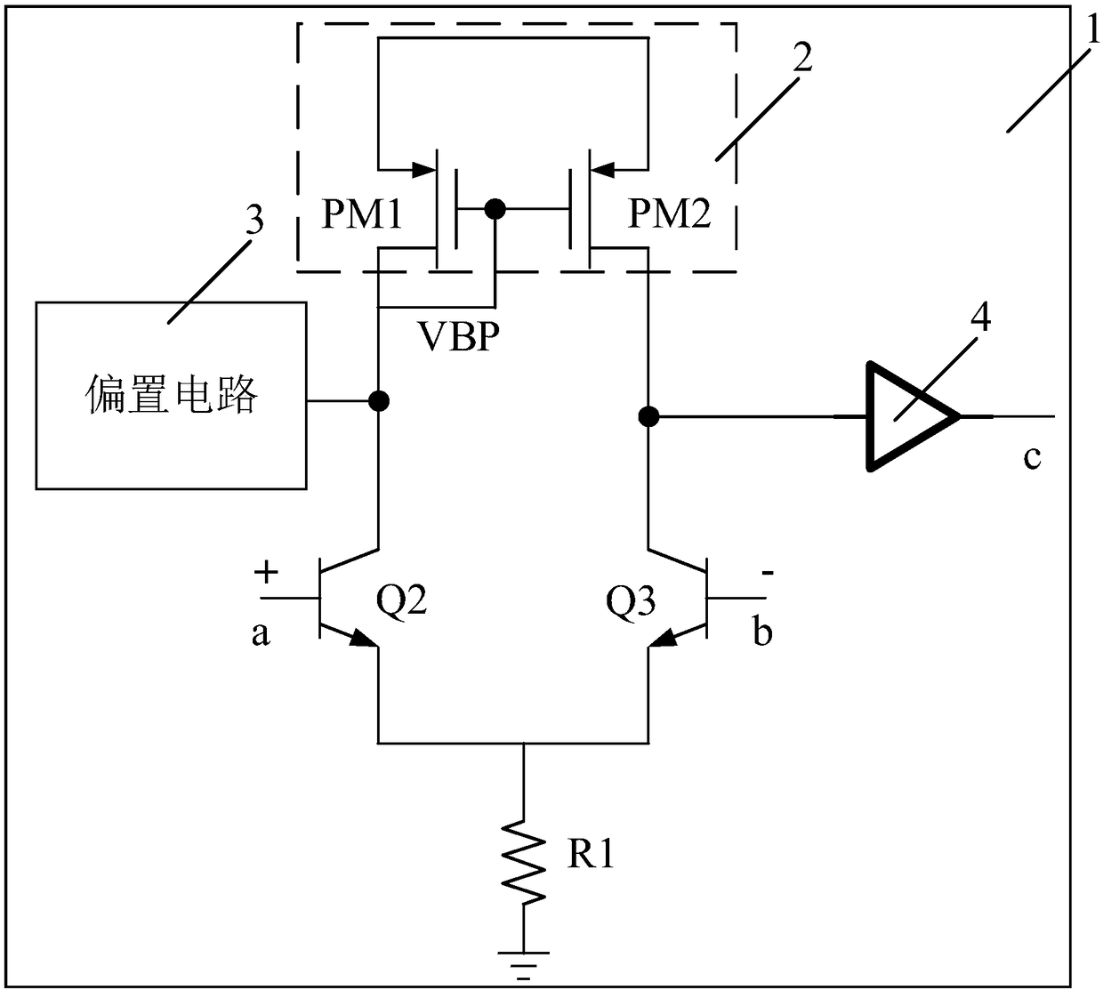
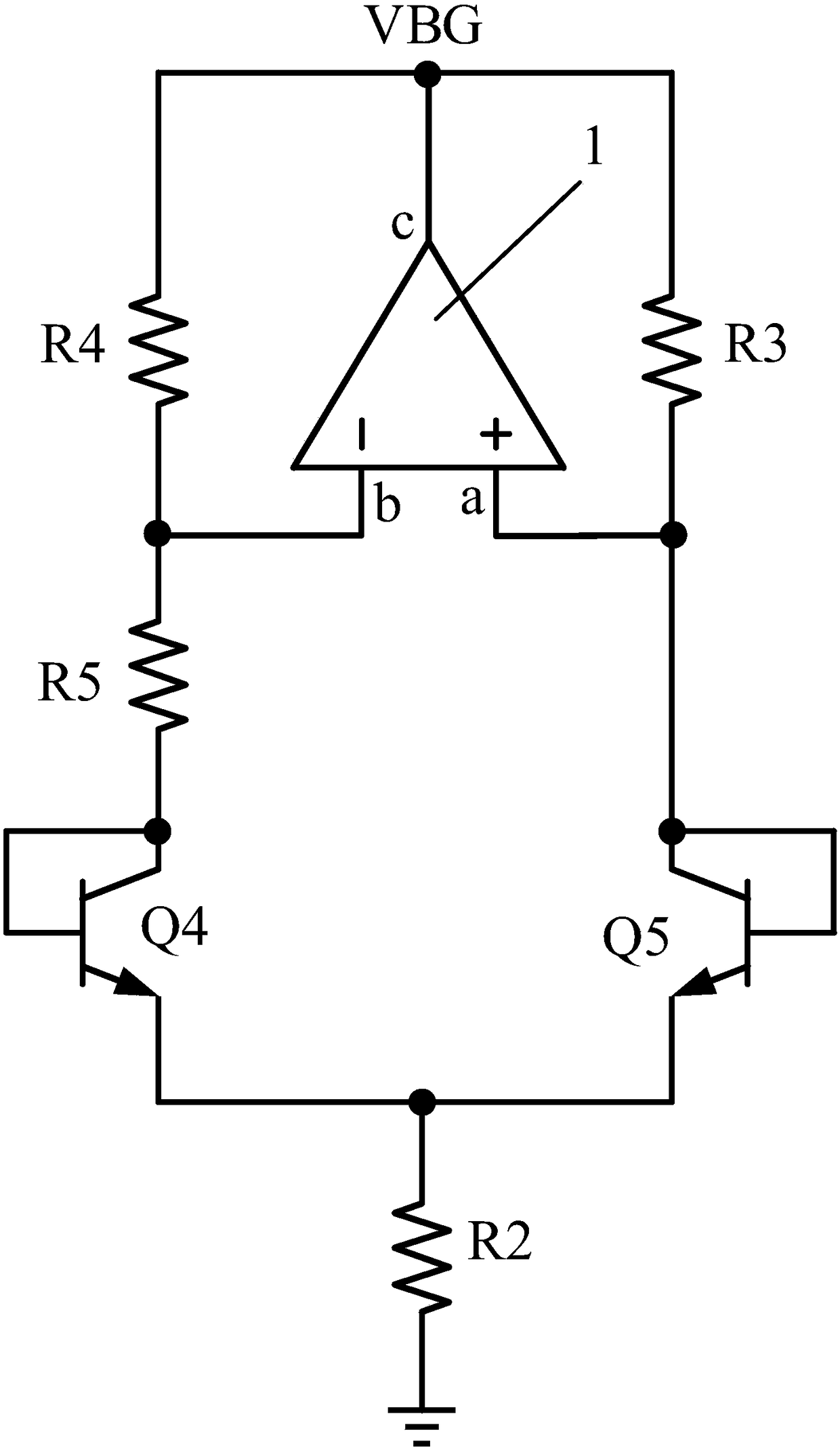
[0052] Such as figure 2 with image 3 As shown, the operational amplifier 1 for the bandgap reference circuit of this embodiment includes a first input terminal a, a second input terminal b, a first output terminal c, a power supply circuit 2, a bias circuit 3, a buffer 4, and a first input terminal a. A resistor R1.

[0053] The first input end a includes a first triode Q2, and the second input end b includes the second triode Q3.

[0054] Wherein, the first triode Q2 and the second triode Q3 are both NPN type triodes; and the emitter area of ​​the first triode Q2 is larger than the emitter area of ​​the second triode Q3 area. That is, compared with the traditional operational amplifier, the first input terminal a and the second input terminal b of the operational amplifier 1 use transistors with different emitter area...


PUM


Abstract

The invention discloses a band-gap reference circuit and an operational amplifier thereof. The operational amplifier comprises a first input end, a second input end and a first output end, and furthercomprises a power supply circuit; the first input end comprises a first audion, and the second input end comprises a second audion; the area of an emitter of the first audion is larger than that of an emitter of thee second audion; the first output end is used for outputting driving voltage. By improving the operational amplifier in the band-gap reference circuit, the structure of the operationalamplifier in an existing band-gap reference circuit is simplified, and gain errors of the circuit caused by mismatching of the operational amplifier are reduced; meanwhile, the structure is simple, an additional biasing circuit is not needed, thus an additional circuit structure is not needed, and the current loss is reduced.

Description

Technical field [0001] The invention relates to the technical field of integrated circuit design, in particular to a band gap reference circuit and an operational amplifier thereof. Background technique [0002] Such as figure 1 Shown is an existing bandgap reference circuit, which uses the base-emitter voltage difference VBE of an NPN transistor as a bandgap reference circuit with a positive temperature coefficient. The band gap reference circuit is mainly based on the correlation between the saturation current Is of the transistor Q0 and the transistor Q1 and the band gap energy of the semiconductor material, as shown in the following formula: [0003] [0004] Where V T =KT / q; [0005] I C Represents the collector current of the triode, V T Represents the voltage equivalent of temperature; K is Boltzmann's constant 1.38×10^-23J / K, T is the thermodynamic temperature, that is, the absolute temperature (300K), and q is the electronic charge 1.6×10^-19C. At room temperature, V T ≈26...

Claims


Application Information

Patent Timeline
Patent Type & Authority Applications(China)
IPC IPC(8): G05F1/575
CPCG05F1/575
Inventor 向飞翔常祥岭赵海亮谢雪松陶园林
Owner SHANGHAI BEILING
Why Eureka
Try Eureka