
A wireless mobile terminal and antenna

An antenna and antenna arm technology, applied in the field of communication applications, can solve problems such as narrow wireless coverage and narrow radiation lobe, achieve good product competitiveness, increase radiation directionality and gain, and improve wireless transmission distance and spatial wireless coverage. range effect

Active Publication Date: 2020-02-07
VIVO MOBILE COMM CO LTD
View PDF3 Cites 0 Cited by
  • Summary
  • Abstract
  • Description
  • Claims
  • Application Information

AI Technical Summary

Problems solved by technology

[0005] The purpose of the present invention is to provide a wireless mobile terminal and antenna to solve the problem that the existing tail flame antenna radiation lobe is often narrow, resulting in narrow wireless coverage, and only supports a single millimeter wave frequency

Method used


Image

  • A wireless mobile terminal and antenna
  • A wireless mobile terminal and antenna
  • A wireless mobile terminal and antenna

Examples


Embodiment Construction

[0017] In order to make the technical problems, technical solutions, and advantages to be solved by the present invention clearer, the following will describe in detail with reference to specific embodiments and drawings.

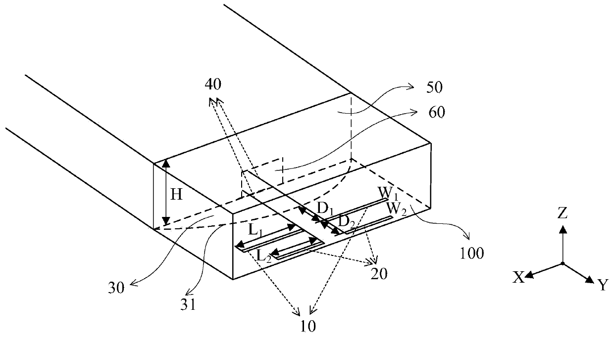
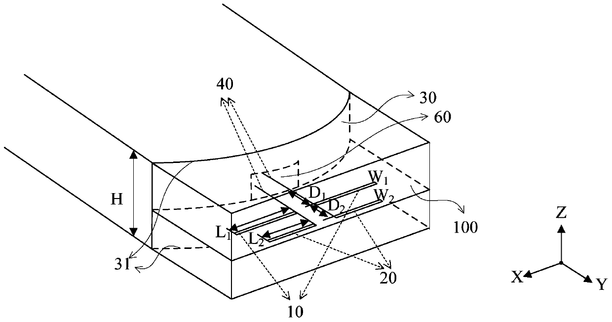
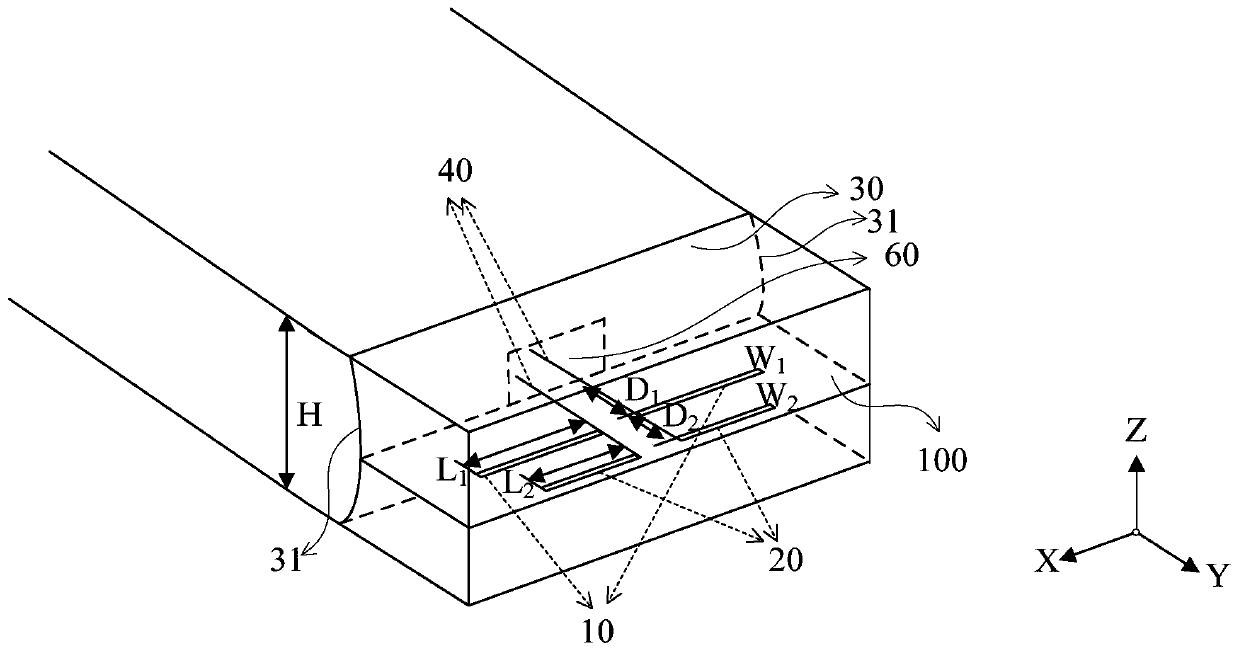
[0018] In some embodiments of the present invention, an antenna is provided, such as Figure 1 to Figure 3 Shown, including:

[0019] The first antenna 10, the first antenna 10 works in the first millimeter wave frequency band;

[0020] The second antenna 20, the second antenna 20 is located on the first side of the first antenna 10, the second antenna 20 works in a second millimeter wave frequency band, and the frequency in the second millimeter wave frequency band is greater than that of the Frequency in the first millimeter wave band;

[0021] The metal surface 30 disposed on the second side of the first antenna 10 includes at least one curved edge 31, and the at least one curved edge 31 is curved toward the direction where the first antenna 10 is located. An ...


PUM


Abstract

Provided are a wireless mobile terminal and an antenna. The antenna of the present disclosure comprises: a first antenna, wherein the first antenna operates on a first millimeter-wave frequency band; a second antenna, wherein the second antenna is located at a first side of the first antenna, the second antenna operates on a second millimeter-wave frequency band, and the frequency within the second millimeter-wave frequency band is greater than the frequency within the first millimeter-wave frequency band; and a metal face, wherein the metal face is provided at a second side, away from one side of the second antenna, of the first antenna, the metal face comprises at least one bending edge, the at least one bending edge bends in the direction in which the first antenna is located, and the first antenna is located between the second antenna and the bending edge.

Description

Technical field [0001] The invention relates to the technical field of communication applications, in particular to a wireless mobile terminal and an antenna. Background technique [0002] As the pace of 5G (fifth generation mobile communication) is getting closer, the demand for 5G-related antennas is becoming increasingly strong and attracting attention. Among them, the most challenging and novel terminal antenna design is the millimeter wave antenna array design. In order to have better antenna radiation coverage, millimeter wave antenna arrays are often composed of antenna elements with complementary radiation patterns (such as tail-flame or end-fire and broadside) antenna elements. And in order to overcome the path loss of the millimeter wave high frequency, the millimeter wave antenna array hopes to have better gain on the radiation lobes in all directions in the space to achieve a better wireless transmission distance. Therefore, the design of millimeter wave antennas is ...

Claims


Application Information

Patent Timeline
Patent Type & Authority Patents(China)
IPC IPC(8): H01Q1/36H01Q1/50H01Q19/02H01Q19/10H01Q21/00H01Q21/30
CPCH01Q1/36H01Q1/50H01Q19/02H01Q19/104H01Q21/0006H01Q21/30
Inventor 黄奂衢
Owner VIVO MOBILE COMM CO LTD
Learn More