Split hoop spacer

A spacer and split-type technology, which is applied in the direction of the device for maintaining the distance between parallel conductors, can solve the problems of easy generation of air holes, trachoma, low production efficiency, scrapping of spacer bars, etc., and achieves improved connection reliability, simple structure, and reduced production. cost effect

Pending Publication Date: 2018-07-17
JIANGSU TIANNAN ELECTRIC POWER EQUIP
View PDF0 Cites 2 Cited by
  • Summary
  • Abstract
  • Description
  • Claims
  • Application Information

AI Technical Summary

Problems solved by technology

With the rapid development of the power industry and the continuous growth of electricity demand, the requirements for high-voltage transmission lines are getting higher and higher. In the squirrel cage jumper of the UHV transmission line steel pipe skeleton, in order to support the jumper and prevent whipping between jumpers In order to prevent impact and collision, hoop-type spacers are required on the steel pipe skeleton. The existing hoop-type spacers are generally made of cast steel for integral casting, and pores and trachoma are prone to occur during pouring; because the pouring is an integral structure, thus A small trachoma in one part will lead to the scrapping of the entire spacer, resulting in low production efficiency, low pass rate, low versatility, and low strength. Each product needs to be molded separately, and the cost of mold making is relatively high. Due to the overall structure, It cannot be disassembled and has a large volume, which is difficult for installation workers to operate at high altitudes; for high-voltage transmission lines, the existing integrally cast hoop spacer is difficult to meet the requirements, so it is necessary to design a split hoop spacer to meet High Voltage Transmission Line Requirements

Method used


Image

  • Split hoop spacer
  • Split hoop spacer
  • Split hoop spacer

Examples


Embodiment Construction

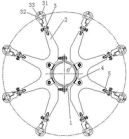
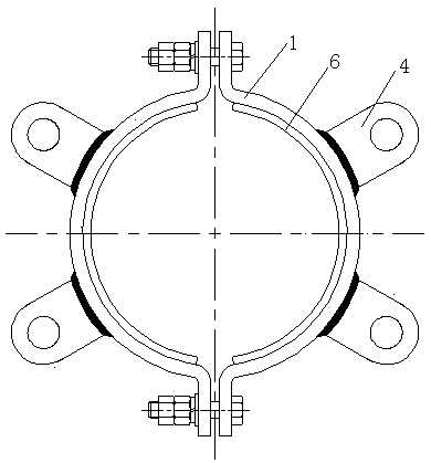
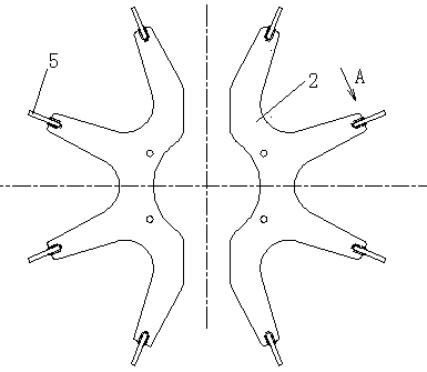
[0018] Reference attached figure 1 , Attached figure 2 , Attached image 3 , Attached Figure 4 , A split type hoop spacer of the present invention is composed of hoop 1, frame plate 2, wire clamp 3, frame plate connecting seat 4, wire clamp connecting plate 5, and non-slip pad 6. The hoop 1 is Two symmetrical semicircular rings are connected by bolts to form a circular ring hoop, and two frame plate connection seats 4 are welded on the semicircular ring; an anti-skid pad 6 is provided on the inner surface of the hoop 1. And the contact surface between the anti-skid pad 6 and the frame is provided with anti-skid patterns; the frame plate 2 is connected with the frame plate connecting seat 4 by bolts; the frame plate 2 is an arc-shaped plate body with a toothed structure; The connecting plate 5 is inserted into the groove of the toothed structure end of the frame plate 2 and welded to form a whole; the wire clamp 3 is arranged on the wire clamp connecting plate 5; the hoop 1 is...


PUM


Abstract

The invention relates to a split hoop spacer, which is formed by a hoop, frame plates, wire clamps, frame plate connecting bases, wire clamp connecting plates and a non-slip mat. The inner surface ofthe hoop is provided with the non-slip mat, and the contact surface of the non-slip mat and the skeleton is provided with antiskid lines. The frame plates are connected with the frame plate connectingbases through bolts; and each frame plate is an arc plate body with a toothed structure. Since the frame plates are formed through overall cutting of a steel plate, support strength is improved, dieopening is prevented, and production cost is reduced; since the hoop is internally provided with the non-slip mat, connection reliability between the whole spacer and the steel pipe skeleton is improved, and easy rotation is not caused; since the contact surface between each rubber tile and a jumper wire is provided with antiskid lines matched with the outer shape of the jumper wire, the jumper wire is not easy to play with respect to the corresponding wire clamp; and since the hoop spacer is in a split structure, the split hoop spacer is high in university and convenient to construct, and hasa great practical and promotional value.

Description

Technical field [0001] The invention relates to the technical field of high-voltage power transmission lines, in particular to a split type hoop spacer. Background technique [0002] After searching the relevant patent documents, no split type hoop spacer with the same structure as the present invention has been retrieved. With the rapid development of the power industry and the continuous growth of electricity demand, the requirements for high-voltage transmission lines are getting higher and higher. In the squirrel cage jumpers of the steel tube frame of UHV transmission lines, in order to support the jumpers and prevent the jumpers from whip For impact and collision, hoop spacer rods are required on the steel pipe frame. The existing hoop spacer rods are generally made of cast steel by integral casting, which is prone to porosity and trachoma during casting; because the casting is an integral structure, A small trachoma in one part will cause the entire spacer to be scrapped,...

Claims


Application Information

Patent Timeline
IPC IPC(8): H02G7/12
CPCH02G7/12
Inventor 姚建生朱小强曹建平
Owner JIANGSU TIANNAN ELECTRIC POWER EQUIP
Why Eureka
Try Eureka