
A rotary nut cracker

A shell breaking machine and rotary technology, which is applied in the field of food processing, can solve the problems of high energy consumption, low crushing efficiency, and large space occupied by equipment installation, so as to achieve the effects of ensuring economic value, saving working time and improving work efficiency

Active Publication Date: 2021-03-09
RUSHAN JINGUO PEANUT PROD +1
View PDF13 Cites 0 Cited by
  • Summary
  • Abstract
  • Description
  • Claims
  • Application Information

AI Technical Summary

Problems solved by technology

The existing nut shelling machinery has the disadvantages of non-adjustable spacing, slow speed, and the need for a large amount of manpower assistance. The effect and efficiency of breaking hard shells are relatively low, and the integrity rate of nuts is not ideal.
In terms of nut grading, the existing technology is to use a graded barrel-shaped screen with holes of different diameters on it, and rotate the screen barrel to achieve the purpose of grading. During the process, it is easy to cause the problem that the nuts block the screen holes
[0003] In the prior art, two different equipments are often used for grading and shelling of nuts. When shelling ungraded nuts is simply cracked with a shelling machine, due to the difference in the diameter of the nuts, the crushing is uneven and the crushing efficiency is low.
When using the method of grading first and then cracking the shells to process nuts, the nuts need to be graded and cracked separately. Due to the use of two sets of equipment, the energy consumption increases and the equipment installation takes up a lot of space, which brings many problems to production and use. inconvenient

Method used


Image

  • A rotary nut cracker
  • A rotary nut cracker

Examples


Embodiment Construction

[0021] Further detailed explanation through specific implementation mode below:

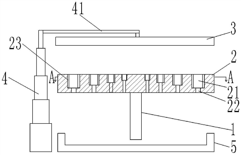
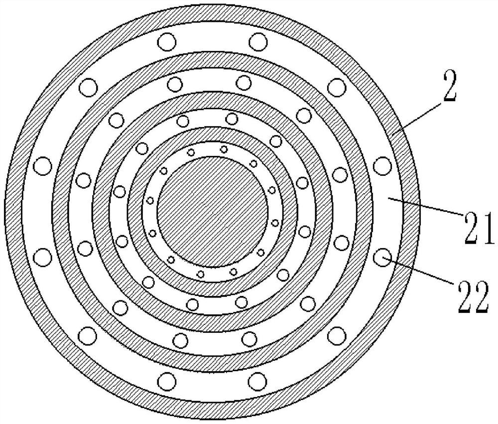
[0022] The reference numerals in the drawings of the description include: supporting device 1 , containing device 2 , annular groove 21 , through hole 22 , air bag 23 , pressure plate 3 , telescopic device 4 , connecting rod 41 , and recovery groove 5 .

[0023] Such as figure 1 A rotary nut cracking machine shown includes a supporting device 1, and the upper end of the supporting device 1 is rotatably equipped with an accommodating device 2. The accommodating device 2 in this embodiment is set as a disc, and the upper surface of the accommodating device 2 is Four annular grooves 21 are provided. The centers of the annular grooves 21 coincide but the radii gradually increase. The width and depth of the annular grooves 21 increase one by one with the increase of the radius of the annular grooves 21 . Airbags 23 are installed on both side walls of the annular groove 21, and the airbags 23 are made...


PUM


Abstract

The invention discloses a rotary nut cracking machine, which comprises a supporting device. The upper end of the supporting device is provided with a receiving device which is rotatably mounted on the upper end of the supporting device. The upper surface of the receiving device is provided with a plurality of annular grooves, and the centers of the ring grooves coincide with each other. However, the radius gradually increases, and the width and depth of the annular groove gradually increase with the increase of the radius of the annular groove. The bottom of the annular groove is provided with several through holes, and the diameter of the through holes increases with the increase of the width of the annular groove. A recovery tank is provided under the supporting device, and a telescopic device is provided on the left side of the recovery tank. The upper end of the telescopic device is connected with a connecting rod, and the connecting rod is connected with a pressure plate located directly above the receiving device. The shape and size of the lower surface of the pressure plate are consistent with the shape and size of the upper surface of the accommodating device. The present invention can satisfy the demand for shell breaking of nuts, can also classify nuts, save working time and manpower, and can make full use of the economic value of nuts to bring more economic benefits to users.

Description

technical field [0001] The invention relates to the technical field of food processing, in particular to a rotary nut shell breaking machine. Background technique [0002] Nut shelling machines usually have stamping type and pressing plate type. The stamping shell breaking uses a punch and a mold to punch the nuts with a certain pressure and spacing, so as to achieve the purpose of breaking the shell. The pressure plate type uses two parallel steel plates to squeeze each other to break the shell. The existing nut shelling machines have the disadvantages of non-adjustable spacing, slow speed, a large amount of manpower assistance, low effect and efficiency of cracking hard shells, and unsatisfactory nut integrity rate. In terms of nut grading, the existing technology uses a graded barrel-shaped screen with holes of different diameters on it, and rotates the screen barrel to achieve the purpose of grading. This kind of equipment has the disadvantages of high energy consumpti...

Claims


Application Information

Patent Timeline
Patent Type & Authority Patents(China)
IPC IPC(8): A23N5/00B07B13/05
CPCA23N5/00B07B13/05
Inventor 孙洪
Owner RUSHAN JINGUO PEANUT PROD
Learn More