Test tube storage rack for medical clinical laboratory

A technology for laboratories and storage racks, which is applied in the field of medical devices, can solve problems such as insufficient sealing of the joints at the open ends of test tubes, lack of protection measures for test tubes, and easy pollution, so as to improve the flexibility of use, reduce the workload, and facilitate Effects of installation and removal treatments

Inactive Publication Date: 2018-07-20
李振
View PDF8 Cites 4 Cited by
  • Summary
  • Abstract
  • Description
  • Claims
  • Application Information

AI Technical Summary

Problems solved by technology

[0003] However, the existing test tube storage racks have some deficiencies during use. On the one hand, the sealing of the joints of the open ends of the test tubes is not perfect, and pollution is prone to occur. On the other hand, there is a lack of corresponding protection measures for the test tubes. , leading to the phenomenon that the test tube is prone to breakage

Method used


Image

  • Test tube storage rack for medical clinical laboratory
  • Test tube storage rack for medical clinical laboratory
  • Test tube storage rack for medical clinical laboratory

Examples


Embodiment 1

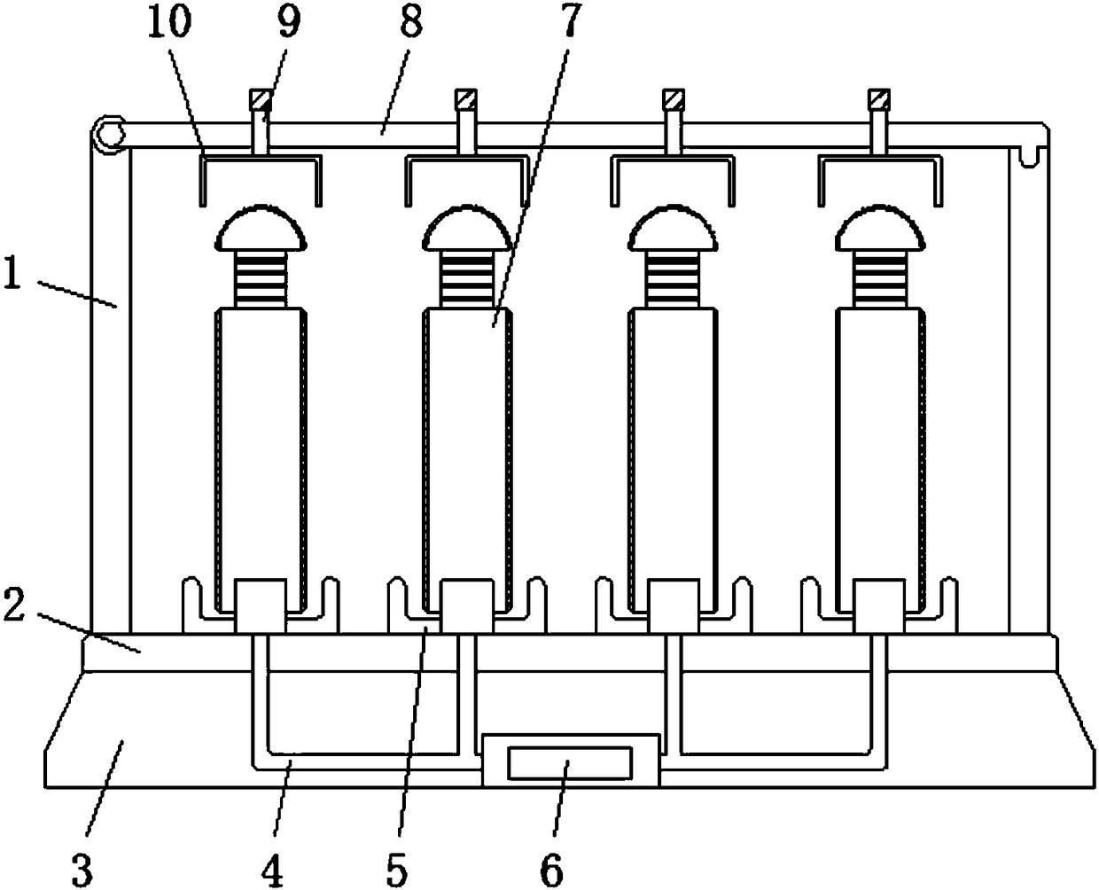
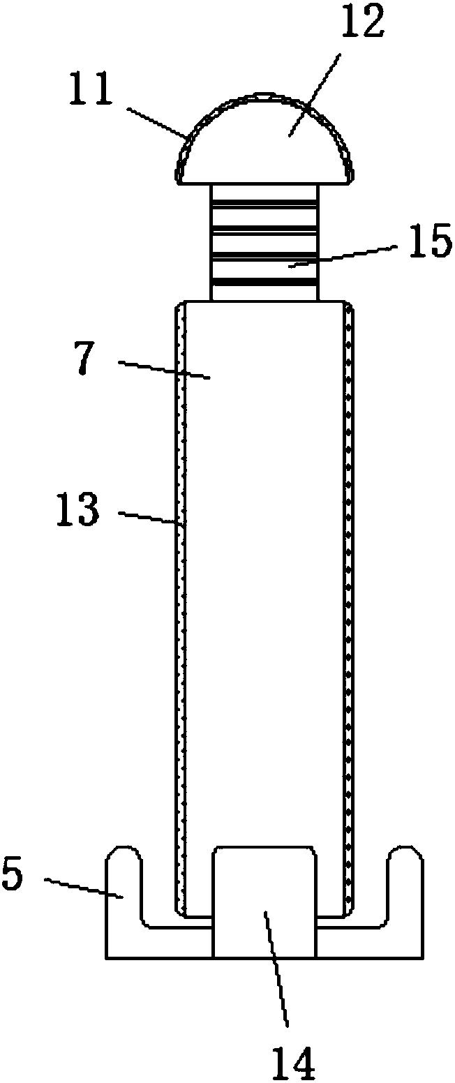
[0023] Embodiment one, with reference to Figure 1-4 , a test tube storage rack for medical laboratories, comprising a base 3, the top of the base 3 is fixed with brackets 1 by bolts on both sides, and the top of one side of the bracket 1 is movably connected with one end of the sealing plate 8 through a pin shaft, and the sealing plate 8 The other end is connected with the card groove opened on the top of the other side bracket 1, the inside of the sealing plate 8 is provided with a threaded rod 9, and the bottom of the threaded rod 9 is provided with a sealing tube 10, and the upper surface of the base 3 is equidistantly provided with a sealing plate 5 , the upper surface of both sides of the horizontal end of the sealing plate 5 is provided with grooves 19, the center of the upper surface of the horizontal end of the sealing plate 5 is provided with a sleeve rod 7, and the inner bottom of the sleeve rod 7 is provided with a battery 14, and the battery 14 passes through the w...

Embodiment 2

[0024] Embodiment two, refer to Figure 1-4 , the inner diameters of the sealing plate 5 and the sealing tube 10 are equal in size, which can hold and seal the upper and lower sides of the test tube stably, and also avoid the shaking of the test tube, thereby avoiding the contamination of the test tube.

Embodiment 3

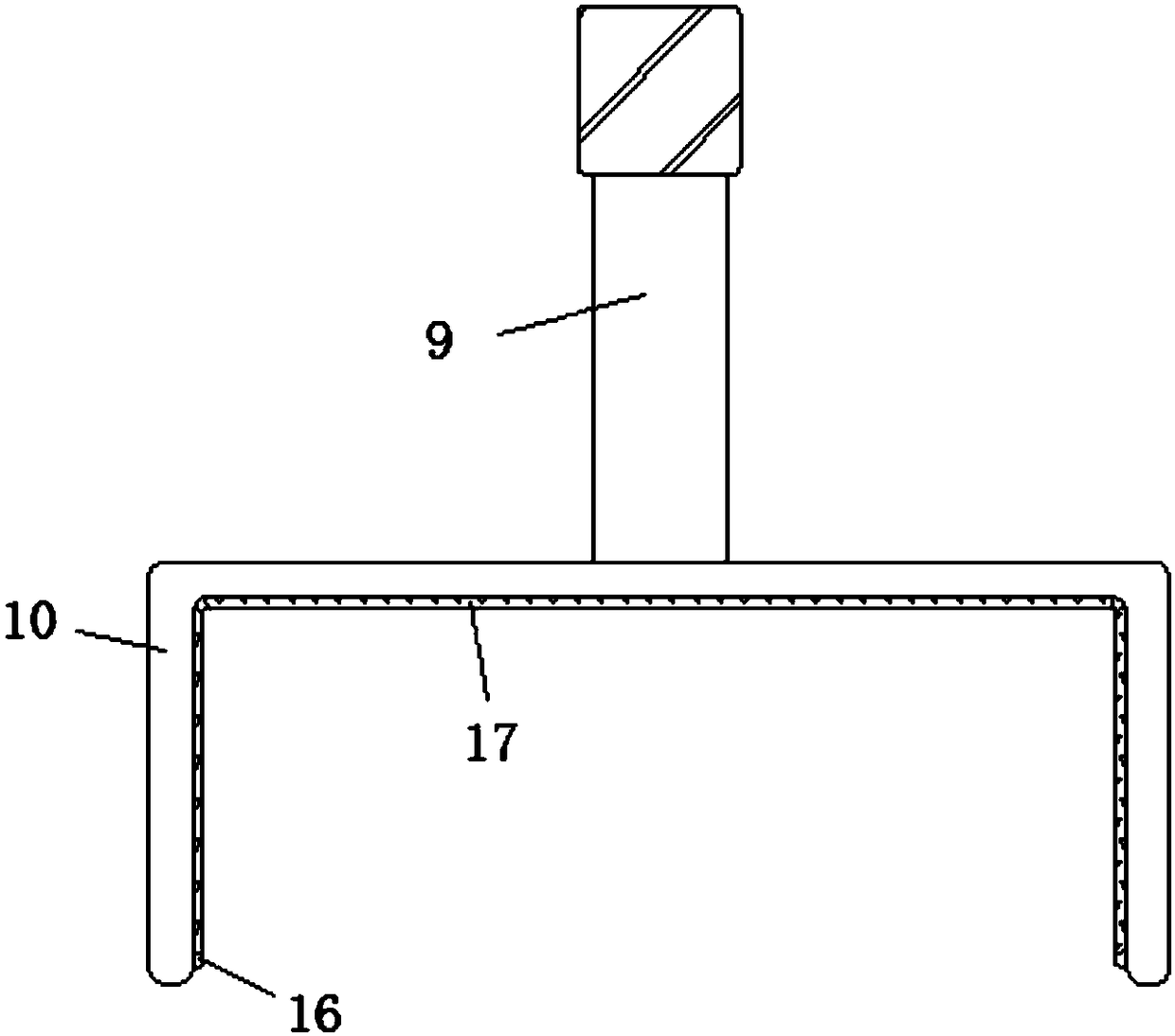
[0025] Embodiment three, refer to figure 1 and image 3 , the inner surface wall of the sealing tube 10 is adsorbed and connected with the soft rubber gasket 17 through the suction cup 16. There are four suction cups 16 in total, and the four suction cups 16 are respectively located at the lower edge of the two sides of the sealing tube 10 and at the joints of the two corners. On the one hand, the suction cup 16 can stably absorb the soft rubber gasket 17, and on the other hand, the suction cup 16 can also absorb different protective gaskets to protect the test tube.


PUM


Abstract

The invention discloses a test tube storage rack for a medical clinical laboratory. The test tube storage rack comprises a base, a supporting bracket is fixed on both sides of the top of the base through bolts, the top of one side of the supporting bracket is movably connected to one end of a sealing plate through a pin roll, batteries are arranged at the inner bottom ends of loop bars, the batteries are connected with ultraviolet disinfection lamps on the outer surfaces of the loop bars through wires, elastic rods are arranged at the tops of the loop bars, contact heads are arranged at the tops of the elastic rods, a heater is fixed to the inner center of the base through bolts, and the heater is connected to heat dissipating covers on the outer surfaces of the contact heads through heatconduction pipes. According to the test tube storage rack, through arrangement of the sealing plate, when test tubes sleeve the surfaces of the loop bars, openings at the lower ends of the test tubesare embedded in grooves to squeeze air cushion layers, so that the portions, which are not squeezed, of the air cushion layers are expanded and deformed for sealing protection of opening ends of the test tubes to prevent unnecessary contamination.

Description

technical field [0001] The invention relates to the technical field of medical devices, in particular to a test tube storage rack for medical laboratory. Background technique [0002] The laboratory is a bridge between clinical medicine and basic medicine, including clinical chemistry, clinical microbiology, clinical immunology, hematology, humoral and blood transfusion and other sub-disciplines. In the normal operation of the medical laboratory, test tubes are used Store the relevant reagents and liquids, and then send them into the testing equipment for inspection and processing to obtain reliable medical reference data. When used in the test tube department, the test tubes need to be stored and placed to avoid contamination or damage to the test tubes. Phenomenon. [0003] However, the existing test tube storage racks have some deficiencies during use. On the one hand, the sealing of the joints of the open ends of the test tubes is not perfect, and pollution is prone to ...

Claims


Application Information

Patent Timeline
Patent Type & Authority Applications(China)
IPC IPC(8): B01L9/06A61L2/10
CPCB01L9/06A61L2/10
Inventor 李振
Owner 李振
Why Eureka
Try Eureka