High-efficiency waste oil drum treatment system

A treatment system and waste oil technology, which is applied in the field of high-efficiency treatment systems, can solve problems such as low treatment efficiency and poor treatment effect, and achieve the effects of improving treatment efficiency, reducing labor intensity, and simple steps

Inactive Publication Date: 2018-07-20
重庆澳净环保科技有限公司
View PDF0 Cites 5 Cited by
  • Summary
  • Abstract
  • Description
  • Claims
  • Application Information

AI Technical Summary

Problems solved by technology

[0006] In view of this, the present invention provides a high-efficiency treatment system for waste oil barrels in order to solve the problems of low processing efficiency and poor treatment effect of existing waste oil barrel treatment equipment in the process of treating waste oil barrels

Method used


Image

  • High-efficiency waste oil drum treatment system
  • High-efficiency waste oil drum treatment system

Examples


Embodiment Construction

[0021] The preferred embodiments of the present invention will be described in detail below with reference to the accompanying drawings.

[0022] The reference signs in the accompanying drawings of the specification include:

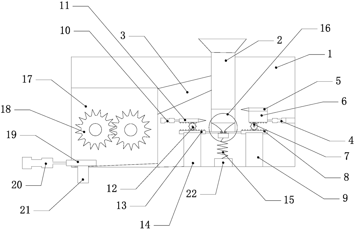
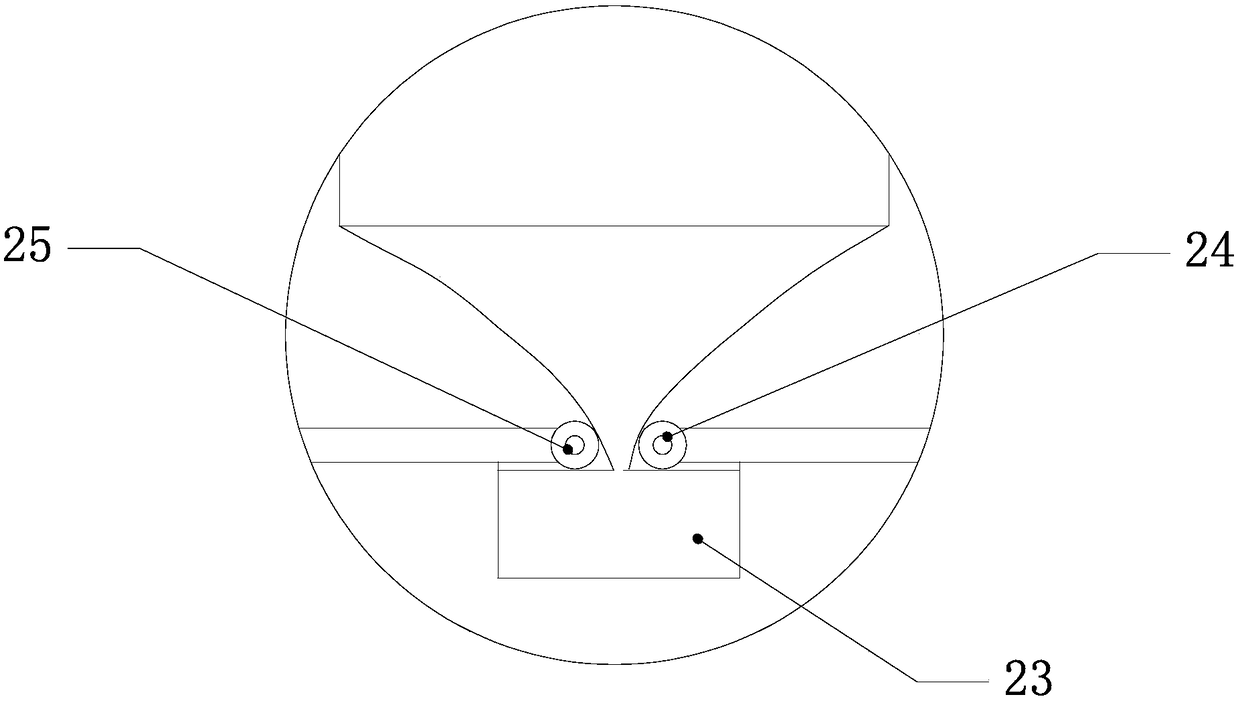
[0023] Frame 1, cutting cylinder 2, discharge pipe 3, first cylinder 4, first cutting knife 5, boss 6, first gear 7, first rack 8, first support column 9, second cylinder 10, The second cutting knife 11, the second gear 12, the second rack 13, the second support column 14, the return spring 15, the lifting block 16, the crushing box 17, the roller gear 18, the oil collection box 19, the third cylinder 20, A discharge conduit 21 , a first support plate 22 , a second support plate 23 , a first roller 24 , and a second roller 25 .

[0024] like Figure 1~2 The shown high-efficiency treatment system for waste oil barrels includes a frame 1, a cutting cylinder 2 and a crushing box 17 arranged on the frame 1, and a discharge port is provided on the side wall...


PUM

PropertyMeasurementUnit
Slopeaaaaaaaaaa

Abstract

The invention belongs to the field of motor vehicle waste disposal and relates to a waste oil drum stage treatment device. The bottom of a cutting barrel is slidably connected with a lifting block suede for lifting cut materials to a discharge port formed in the sidewall of the cutting barrel. The two sides of the bottom of the lifting block are connected with a first cylinder and a second cylinder. The first cylinder is fixedly provided with a boss with a first cutter. A second cutter is fixedly connected to the second cylinder. A first supporting column with a first rack is mounted below theboss. A first gear is engaged between the first rack and a third rack. A second supporting column with a second rack is mounted below a cutter bar of the second cutter. A second gear is engaged between the second rack and a fourth rack. Push rods are mounted on the opposite sides of the first rack and the second rack. Reset springs are arranged below the lifting block. Coupler roller gears are arranged in a crushing tank communicating with the discharge port. An oil recovery box with a cylinder is mounted at the bottom of the crushing tank. The problems that an existing waste oil drum treatment device is low in treatment efficiency and high in labor cost in the waste oil drum treatment process are solved.

Description

technical field [0001] The invention belongs to the technical field of motor vehicle waste treatment, and relates to a high-efficiency treatment system for waste oil drums. Background technique [0002] In recent years, the increase of the motor vehicle market has led to more and more output of motor vehicles. Although automobiles in motor vehicles are an important tool for our travel, with the increase of automobiles, the disposal of scrap oil drums will follow. question. [0003] At present, the emerging enterprises engaged in the recycling of waste barrels in my country do not have a unified industry management. Most of the enterprises are small in scale and have disadvantages such as backward technology, simple equipment, low efficiency, and large pollution. Due to the backward processing technology, personal safety accidents caused by improper equipment operation are not uncommon. [0004] At present, the processing and decomposition equipment for waste oil drums are ...

Claims


Application Information

Patent Timeline
IPC IPC(8): B26F3/00B26D5/12B02C4/08B02C4/28
CPCB02C4/08B02C4/28B02C2201/06B26D5/12B26F3/00
Inventor 何德树何星锦何思颖
Owner 重庆澳净环保科技有限公司
Why Eureka
Try Eureka