Wear plate of eddy current rail brake system, system and manufacturing method thereof
A technology of a braking system and a manufacturing method, applied in the field of wear plates, can solve problems such as loss of braking force, inability of a natural eddy current braking system to work, and achieve the effects of eliminating magnetic gaps, preventing displacement, and enhancing eddy current effects
- Summary
- Abstract
- Description
- Claims
- Application Information
AI Technical Summary
Problems solved by technology
Method used
Image
Examples
Embodiment 1
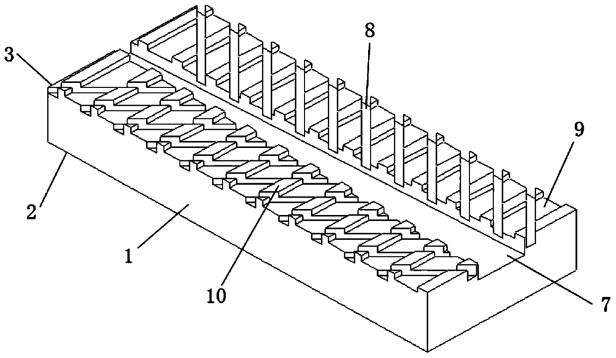
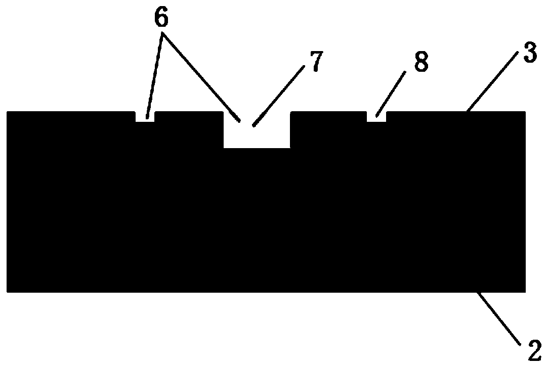
[0064] The Cu-1wt.% Fe alloy (heat conduction part 5) and nylon (wear part 4) are compounded according to the volume fraction of 80% and 20% respectively to prepare wear plate 11, the thickness and width of heat conduction part 5 and wear part 4 Respectively consistent, the length of the heat conducting part 5 is 16 mm, the length of the wear part 4 is 4 mm, and the front end of the wear plate 11 in the length direction is the wear part 4 . The wear plate 11 has a total thickness of 10 mm, a width consistent with the width of the rail surface, and a length consistent with the length of the magnetic system unit. Groove one side of the wear plate 11, wherein the main air passage 7 has a width of 2 mm and a depth of 2 mm; the auxiliary air passage 8 in the direction of +45 degrees has a width of 1 mm and a depth of 1 mm. Such as Figure 4 As shown, the connecting portion 2 of the wear plate 11 is fixed to the magnetic system unit, and the fixing method can be adhesive or mechani...
Embodiment 2
[0066] Composite Cu-10wt.% Fe (heat conducting part 5) alloy and polyimide (wearing part 4) according to the volume fraction of 60% and 40% respectively to prepare wearing plate 11, alloy block (heat conducting part 5) and polyimide The thickness and width of the imide block (wear-resistant part 4) are the same, the length of the alloy block (heat-conducting part 5) is 6 mm, and the length of the polyimide block (wear-resistant part 4) is 4 mm, at the front end of the wear plate 11 in the length direction It is a polyimide block (wear part 4). The wear plate 11 has a total thickness of 15 mm, a width consistent with the width of the rail surface, and a length consistent with the length of the magnetic system unit. Groove one side of the wear plate 11, wherein the width of the main air passage 7 is 5 mm, and the depth is 5 mm; the width of the auxiliary air passage 8 in the direction of +45 degrees is 3 mm, and the depth is 3 mm. The wear plate connecting portion 2 is fixed to...
Embodiment 3
[0068] Composite Cu-2wt.%Fe-5wt.%Ni alloy (heat conduction part 5) and nylon (wear part 4) according to the volume fraction of 70% and 30% respectively to prepare wear plate 11, alloy block (heat conduction part 5) The thickness and width of the nylon block (wear-resistant part 4) are respectively consistent, the length of the alloy block (heat-conducting part 5) is 7 mm, the length of the nylon block (wear-resistant part 4) is 3 mm, and the front end of the wear plate 11 in the length direction is the nylon block ( Wear parts 4). The total thickness of the wear plate is 10mm, the width is consistent with the width of the rail surface, and the length is consistent with the length of the magnetic system unit. Groove one side of the wearing plate 11, wherein the main air passage 7 has a width of 3 mm and a depth of 3 mm; the auxiliary air passage 8 in the direction of +45 degrees has a width of 2 mm and a depth of 2 mm. The connecting portion 2 of the wearing plate 11 is fixed ...
PUM
| Property | Measurement | Unit |
|---|---|---|
| diameter | aaaaa | aaaaa |
| thickness | aaaaa | aaaaa |
Abstract
Description
Claims
Application Information
 - R&D
- Intellectual Property
- Life Sciences
- Materials
- Tech Scout
- Unparalleled Data Quality
- Higher Quality Content
- 60% Fewer Hallucinations
Browse by: Latest US Patents, China's latest patents, Technical Efficacy Thesaurus, Application Domain, Technology Topic, Popular Technical Reports.
© 2025 PatSnap. All rights reserved.Legal|Privacy policy|Modern Slavery Act Transparency Statement|Sitemap|About US| Contact US: help@patsnap.com


