Lifting type on-site regeneration device for SCR (Selective Catalytic Reduction) catalyst

An SCR catalyst, lift-type technology, applied in the field of flue gas purification, can solve the problems of SCR denitrification catalyst module damage, thin catalyst wall, blockage, etc.

Active Publication Date: 2018-07-20
CHANGSHA UNIVERSITY OF SCIENCE AND TECHNOLOGY
View PDF19 Cites 5 Cited by
  • Summary
  • Abstract
  • Description
  • Claims
  • Application Information

AI Technical Summary

Problems solved by technology

However, the life of the catalyst is generally 3 to 5 years due to surface ash clogging, poisoning, and wear, and the cost of the catalyst is high. Therefore, it is necessary to use the method of catalyst regeneration and activation to reduce the operating cost of the SCR system.
[0004] At present, the regeneration method of SCR denitrification catalyst in coal-fired power plants is to remove the SCR catalyst module and send it to the regeneration factory, and regularly turn over the regenerated SCR catalyst module in the cleaning tank and regeneration tank, because the volume and weight of the catalyst module are relatively large At the same time, the catalyst wall is thin, which is not suitable for strong agitation or transportation. In addition, most of the existing SCR denitrification catalyst regeneration devices are designed and manufactured for each process, resulting in the existing SCR denitrification catalyst regeneration devices occupying an excessively large area and costing construction funds
Moreover, due to the continuity of the regeneration process, it is necessary to move the SCR denitration catalyst module to be regenerated from one device to another for multiple transportations. During the transportation process, it is very easy to cause damage to the SCR denitration catalyst module to be regenerated, thereby affecting regeneration. quality

Method used


Image

  • Lifting type on-site regeneration device for SCR (Selective Catalytic Reduction) catalyst
  • Lifting type on-site regeneration device for SCR (Selective Catalytic Reduction) catalyst
  • Lifting type on-site regeneration device for SCR (Selective Catalytic Reduction) catalyst

Examples


Embodiment Construction

[0026] The present invention will be further described in detail below in conjunction with the accompanying drawings and specific embodiments.

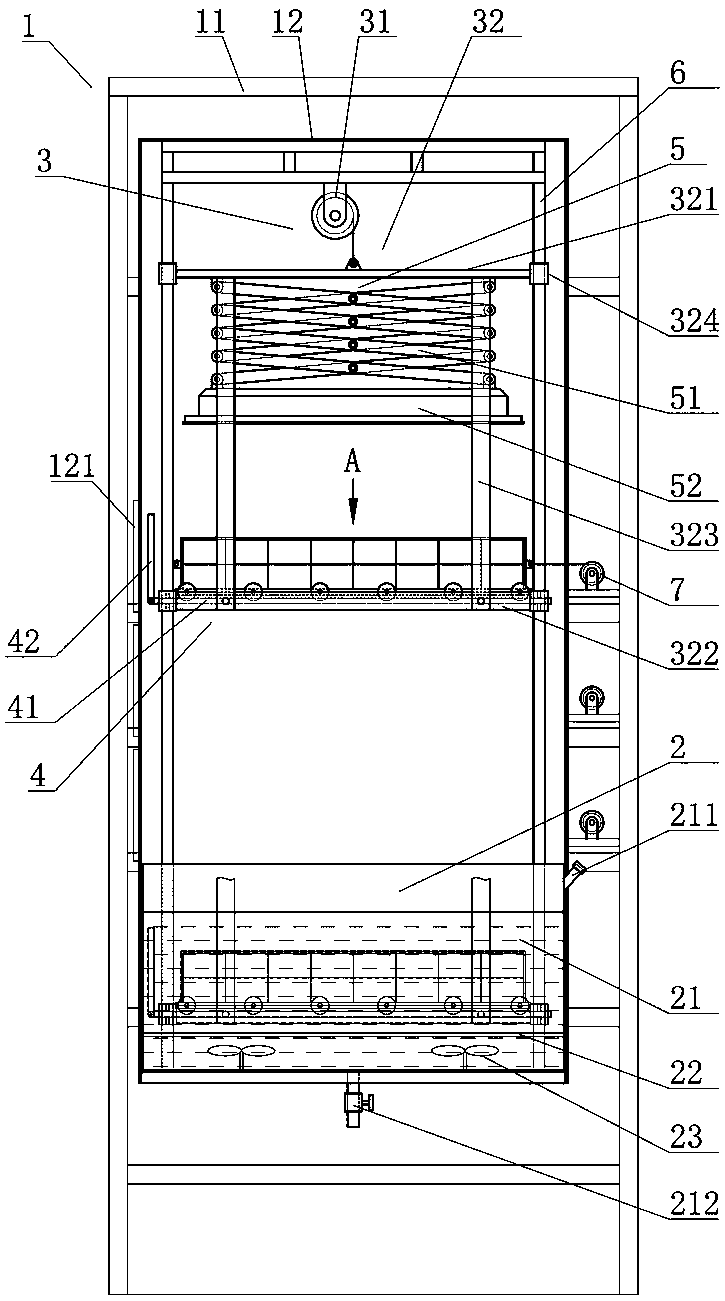
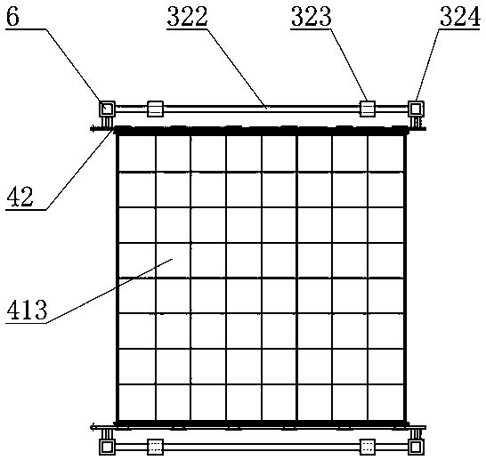
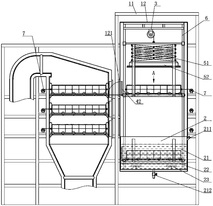
[0027] Figure 1 to Figure 4 It shows an embodiment of the lifting type SCR catalyst on-site regeneration equipment of the present invention, including a fixed support frame 1 docked with the SCR catalyst on-site reaction station, a liquid storage assembly 2 is provided at the bottom of the fixed support frame 1, and a fixed support frame 1 There is a conveying lifting assembly 3 that can extend into the liquid storage assembly 2. The bottom end of the conveying lifting assembly 3 is provided with a butt joint assembly 4 for connecting the SCR catalyst of the reaction station. There is a heating lift assembly 5 for heating the SCR catalyst. When in use, fill the liquid storage assembly 2 with clear water, move the SCR catalyst in the reaction station to the flat joint assembly 4 in the fixed support frame 1, start the conveying lifti...


PUM


Abstract

The invention discloses a lifting type on-site regeneration device for an SCR (Selective Catalytic Reduction) catalyst. The device comprises a fixing supporting frame which is abutted with an SCR catalyst on-site reaction station, wherein a liquid storing assembly is arranged at the bottom end of the fixing supporting frame; a conveying lifting assembly which can extend into the liquid storing assembly is arranged in the fixing supporting frame; an abutting assembly which is abutted with an SCR catalyst at the reaction station is arranged at the bottom end of the conveying lifting assembly; aheating lifting assembly for heating the SCR catalyst is arranged above the abutting assembly on the conveying lifting assembly. The device has the advantages of being simple and compact in structure,short in period, low in cost, small in workload, and high in regeneration quality.

Description

technical field [0001] The invention mainly relates to the field of flue gas purification, in particular to an on-site regeneration equipment for a lift-type SCR catalyst. Background technique [0002] In recent years, with the reduction of my country's environmental capacity and the stricter national emission standards for nitrogen oxides, the pressure to reduce nitrogen oxides is increasing. At present, coal-fired power plants' control of nitrogen oxide emissions is mainly divided into pre-generation control and post-generation control. Pre-generation control mainly includes low-nitrogen combustion technology and re-combustion technology, and post-generation control is mainly divided into dry method and wet method. The post-combustion control of coal-fired power plants in my country mainly adopts the Selective Catalytic Reduction (SCR) method in the dry process, which is applied to the flue gas denitrification system. This technology is basically applied in most power pla...

Claims


Application Information

Patent Timeline
Patent Type & Authority Applications(China)
IPC IPC(8): B66F7/02B66F7/28B01D53/90B01D53/56
CPCB01D53/8625B01D53/90B66F7/02B66F7/28
Inventor 张巍宋权斌
Owner CHANGSHA UNIVERSITY OF SCIENCE AND TECHNOLOGY
Why Eureka
Try Eureka