
A variable flow water pump

A flow and variable technology, applied in the direction of non-variable pumps, coolant flow control, pumps, etc., can solve the problems of large flow loss of cooling medium, large installation space, low energy utilization rate, etc., to improve work efficiency , Improve energy and reduce flow loss

Active Publication Date: 2019-12-13
NINGBO GEELY ROYAL ENGINE COMPONENTS
View PDF1 Cites 0 Cited by
  • Summary
  • Abstract
  • Description
  • Claims
  • Application Information

AI Technical Summary

Problems solved by technology

[0004] But the above-mentioned engine water pump has the following defects: 1. In order to realize blade height adjustment, the impeller in the above-mentioned water pump adopts a semi-open impeller structure. Although it can adjust the pumping capacity of the water pump by changing the blade height, the impeller work efficiency is not high , leading to large flow loss of cooling medium and low energy utilization rate, which is not conducive to energy saving and emission reduction; 2. In the above-mentioned water pump, the matching structure between the temperature-sensitive wax bag, the impeller and the impeller shell is relatively complicated, and the installation space occupied is relatively large. Large, not compact enough, because the water pump is installed in the narrow engine compartment, which is not conducive to the design and layout of the water pump size

Method used


Image

  • A variable flow water pump
  • A variable flow water pump
  • A variable flow water pump

Examples


Embodiment Construction

[0026] The following are specific embodiments of the present invention and in conjunction with the accompanying drawings, the technical solutions of the present invention are further described, but the present invention is not limited to these embodiments.

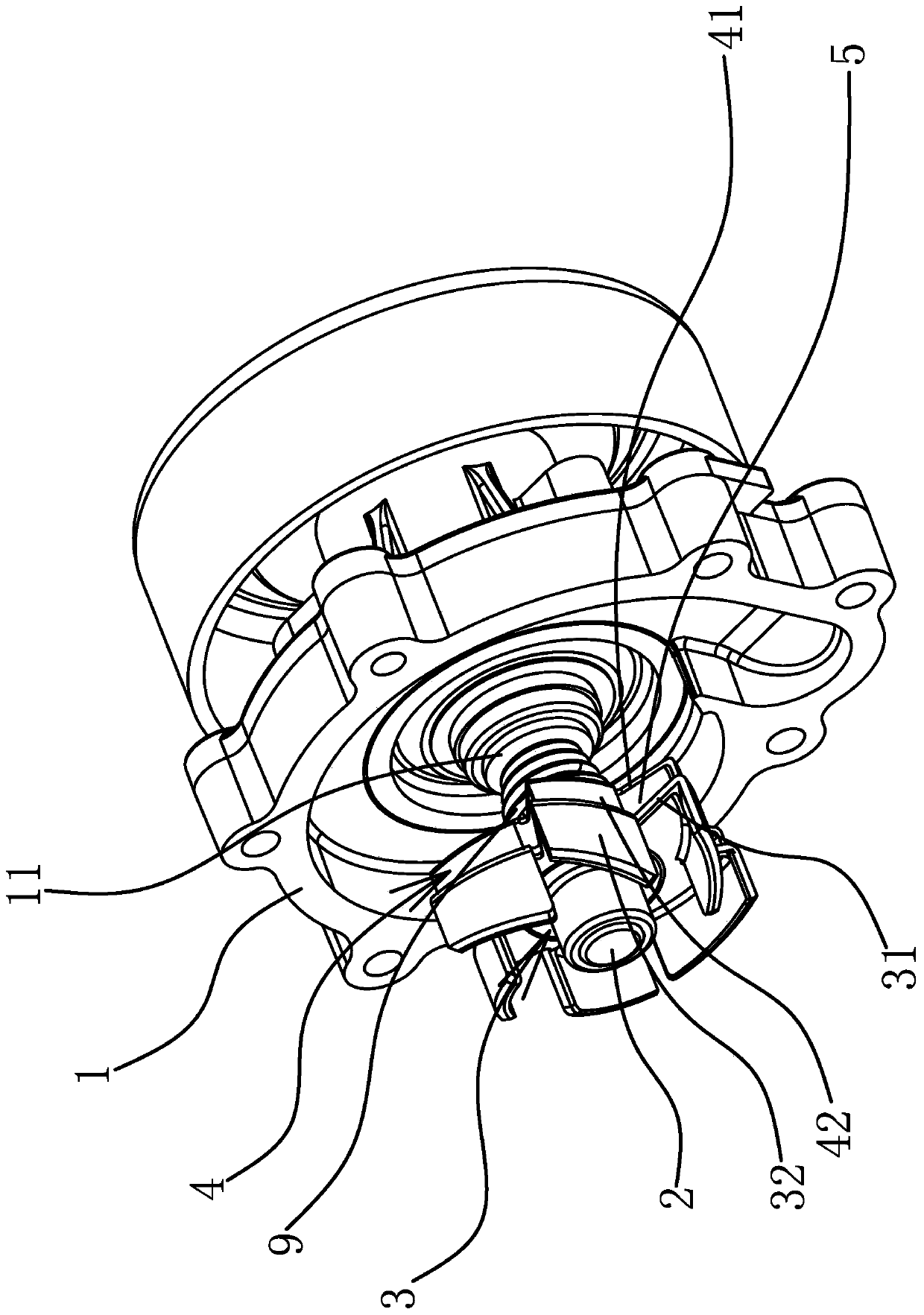
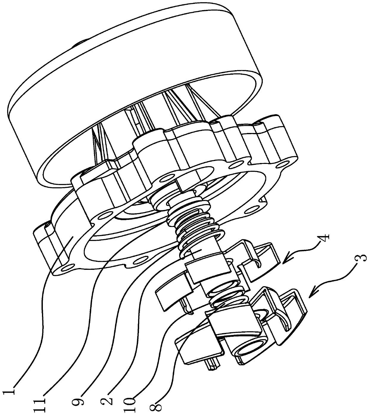
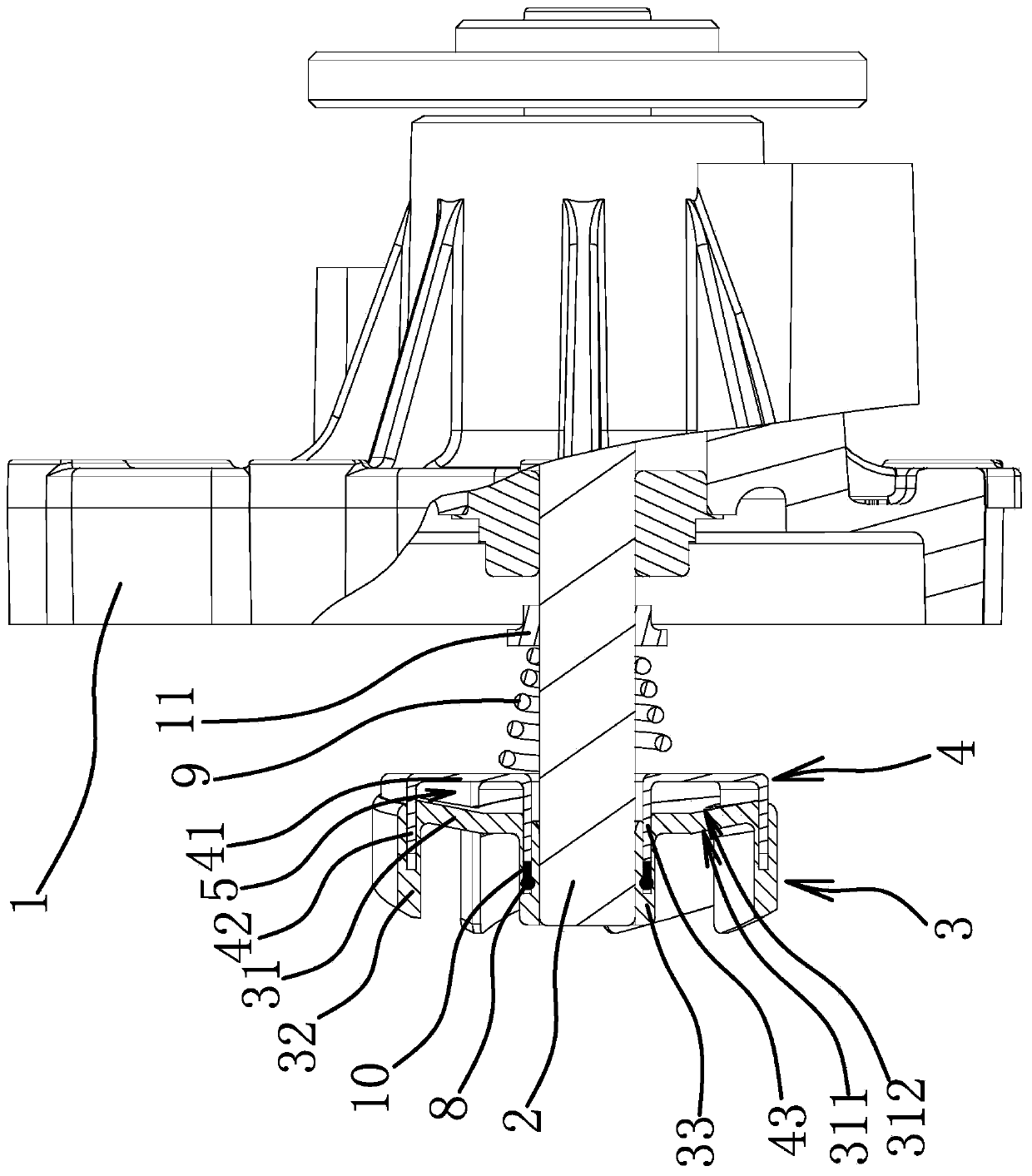
[0027] Specifically, as figure 1 and figure 2 As shown, the variable flow water pump includes a pump casing 1, a pump shaft 2, a main impeller 3 fixedly connected to the pump shaft 2, and an auxiliary shaft sleeved on the pump shaft 2 and arranged coaxially with the main impeller 3 and slidingly connected. The impeller 4, the main impeller 3 and the auxiliary impeller 4 are all open water pump impellers. The main impeller 3 has a main disk 31 and main blades 32 , and the auxiliary impeller 4 has an auxiliary disk 41 and auxiliary blades 42 . Among them, the auxiliary blade 42 corresponds to the main blade 32 one by one and is inserted into the main blade 32 so that a water collection chamber 5 is formed between the auxi...


PUM


Abstract

The invention provides a variable-flow type water pump and belongs to the technical field of automobiles. The variable-flow type water pump solves the problems so as to achieve the aims of meeting thedemands of flow regulation of a cooling medium under different temperature conditions and improving the working efficiency of the water pump at the same time. The water pump comprises a pump shell, apump shaft and a main impeller with a main wheel disc and main blades, wherein an auxiliary impeller coaxial to and slidably connected with the main impeller sleeves on the pump shaft and is providedwith an auxiliary wheel disc and auxiliary blades; the auxiliary blades are in one-to-one correspondence to the main blades and are inserted into the main blades, so that a water collecting chamber is formed between the auxiliary wheel disc and the main wheel disc; and the auxiliary impeller can slide back and forth along an axial direction according to a temperature change of the cooling mediumunder the action of a temperature-sensing regulation structure so as to adjust the insertion amount of the auxiliary blades. Through the design, the water pump flow can be effectively reduced at low water temperature and can be improved at high water temperature, the effects on saving energy and reducing emission are achieved, meanwhile, the normal work of an engine is protected, the working efficiency of the water pump is greatly improved, and an energy-saving effect is greatly improved.

Description

technical field [0001] The invention belongs to the technical field of automobiles and relates to a variable flow water pump. Background technique [0002] The automotive water pump is an indispensable component in the engine cooling system. It mainly provides kinetic energy for the coolant to make the coolant flow in the engine cooling system, so that the coolant can take away the heat generated in the engine system in time. In the prior art, traditional vehicles basically use mechanical water pumps. The mechanical water pumps are driven by an accessory gear train on the engine. The water pump is directly proportional to the rotational speed of the engine, but has nothing to do with the load of the engine. Since the performance of the water pump is based on ensuring that the engine does not overheat, it is usually necessary to linearize the performance based on the highest temperature point of the vehicle or the highest power point of the engine. When the engine is under lo...

Claims


Application Information

Patent Timeline
Patent Type & Authority Patents(China)
IPC IPC(8): F04D29/18F04D29/042F04D15/00F01P5/10F01P7/16
CPCF01P5/10F01P7/16F04D15/0027F04D29/042F04D29/185
Inventor 司纪奎薛国磊宋吉林张元东宋志辉袁爽沈源王瑞平
Owner NINGBO GEELY ROYAL ENGINE COMPONENTS
Learn More