
Magnetorheological damper with complex liquid flow passage structure

A magnetorheological damper, liquid flow channel technology, applied in the direction of shock absorber, shock absorber, spring/shock absorber, etc., can solve the problem that the best effect cannot be achieved, the adjustable range of damping force is narrow, and the size of the damper It can increase the effective damping length, wide dynamic adjustment range, and extend the length.

Active Publication Date: 2018-07-20
EAST CHINA JIAOTONG UNIVERSITY
View PDF8 Cites 4 Cited by
  • Summary
  • Abstract
  • Description
  • Claims
  • Application Information

AI Technical Summary

Problems solved by technology

With the development of high technology, the engineering application of vibration damping system has higher and higher requirements for damping components. Most of the existing magnetorheological dampers are single-channel shear dampers. The flow resistance channel is mainly set inside the coil and between the coil and the sleeve. It is necessary to ensure that the direction of the magnetic field is perpendicular to the flow direction of the magnetorheological fluid, otherwise the best effect cannot be achieved; under this premise, the flow resistance channel must also be The area is as large as possible to obtain sufficient damping force, so its volume is generally relatively large, and the adjustable range of damping force is relatively narrow
[0004] The Chinese invention patent with the publication number CN205118104 U "a magneto-rheological damper with radial flow and circular flow damping channels" proposes a complex damper combined with a magneto-rheological damper and a magneto-rheological valve. The combination of the rheological valve and the magnetorheological damper realizes the complex magnetorheological fluid channel, but this structure has certain limitations. Due to the addition of the valve structure, the axial and radial dimensions of the damper become larger , resulting in bulky size of the whole damper

Method used


Image

  • Magnetorheological damper with complex liquid flow passage structure
  • Magnetorheological damper with complex liquid flow passage structure
  • Magnetorheological damper with complex liquid flow passage structure

Examples


Embodiment Construction

[0017] figure 1 It is a schematic diagram of the structure of the present invention, mainly composed of left lug (1), piston rod (2), damper left end cover (3), damper cylinder (4), piston head left end cover (5), excitation coil (6) , the piston head (7), the right end cover of the piston head (8), the fastening nut (9), the floating piston (10), the right end cover of the damper (11) and the right lifting lug (12).

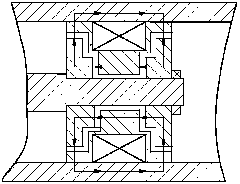
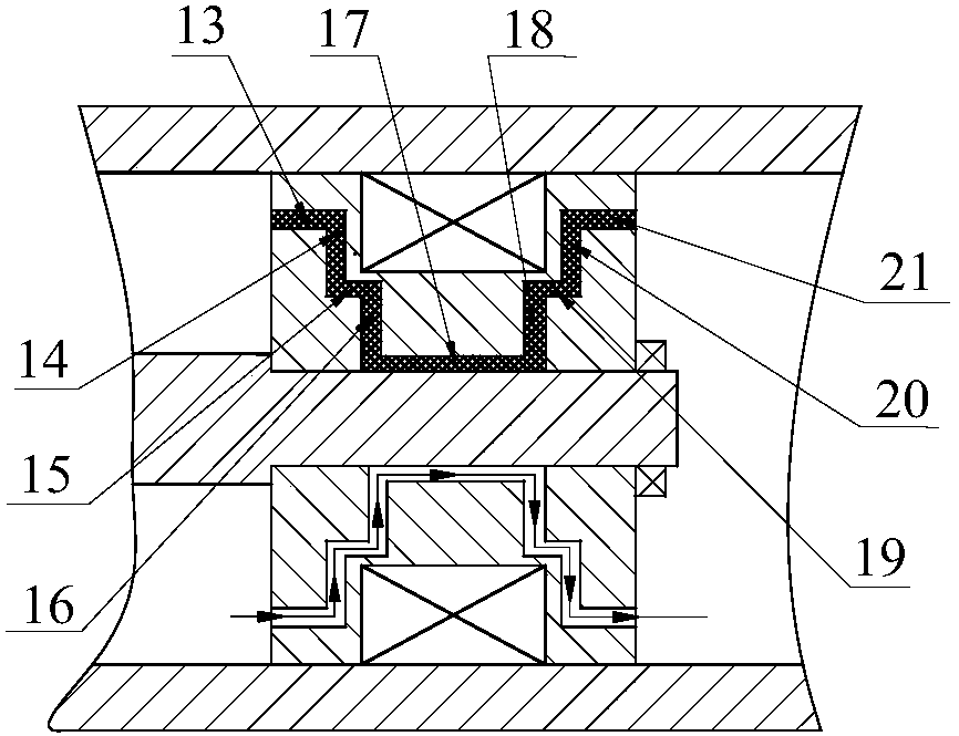
[0018] figure 2It is the magnetic field line distribution diagram of the present invention. Damper cylinder (4), piston head left end cover (5), piston head (7) and piston head right end cover (8) are made of No. 10 steel magnetic material; All the other parts are made of stainless steel non-magnetic material. When the excitation coil (6) is energized, the magnetic field lines generated by electromagnetic induction pass through the left end cover of the piston head (5), the axial circular ring damping gap I (13), and the piston head (7) to the damper cylinder...


PUM


Abstract

The invention discloses a magnetorheological damper with a complex liquid flow passage structure. The magnetorheological damper is mainly composed of a piston rod, damper end covers, a damper cylinderbody, a magnet exciting coil, a piston head left end cover, a piston head right end cover, a piston head and the like. A complex liquid flow passage is formed by gaps defined by the piston head leftend cover, the piston head right end cover and the piston head in an enclosed mode, wherein four effective damping gaps are composed of the axial ring type damping gap I, the axial ring type damping gap V, the radial disc type damping gap II and the radial disc type damping gap III. When the magnet exciting coil is powered on, a definite-size magnetic field is generated in the four effective damping gaps, so that the shearing area and the effective damping length of the damping passage are increased. By the adoption of the complex flowing type liquid flow passage structure, the output dampingforce and the damping force adjustable range of the damper are further improved on the premise of not changing the radial and axial sizes of the damper, and the damper is particularly suitable for vibration isolation systems in the industries of railway, traffic and the like.

Description

technical field [0001] The invention relates to a magnetorheological damper, in particular to a magnetorheological damper with a complex liquid flow channel structure. Background technique [0002] The magnetorheological damper is a new type of semi-active damping device based on the controllable characteristics of magnetorheological fluid. It has the advantages of simple structure, fast response, low power consumption, large damping force and continuous adjustment. At present, magnetorheological dampers have been widely used in vibration and anti-seismic systems of buildings and bridges, railway rolling stock and automobile suspension systems, etc. [0003] In the vibration control system, the magnetorheological damper is mainly used to control the vibration generated by the system components to meet the requirements of various mechanical equipment for various working conditions. Therefore, the performance of the magnetorheological damper directly affects the static and dy...

Claims


Application Information

Patent Timeline
Patent Type & Authority Applications(China)
IPC IPC(8): F16F9/53
CPCF16F9/535
Inventor 胡国良冯海波喻理梵钟芳丁孺琦曹鹏
Owner EAST CHINA JIAOTONG UNIVERSITY
Learn More