
MBUS control circuit for temperature control valve and control method thereof

A control circuit and temperature control valve technology, applied in the valve operation/release device, valve details, valve device and other directions, can solve the problems of energy waste, low utilization rate of large current, bus current jitter, etc. Improved customer satisfaction, reduced outages and duration of outages

Pending Publication Date: 2018-07-20
RUINA INTELLIGENT EQUIP CO LTD
View PDF0 Cites 4 Cited by
  • Summary
  • Abstract
  • Description
  • Claims
  • Application Information

AI Technical Summary

Problems solved by technology

Because of its advantages of non-polarity and convenient construction, MBUS has been used more and more. For example, heating and water supply are widely used, but MBUS is only used for communication, and some enterprises use MBUS for power supply. For example, directly adding a DCDC step-down chip to the back end of the MBUS, the disadvantage of this solution is that when the load current increases, the bus current will fluctuate, causing the MBUS host to receive wrong data; some companies also use the constant current source method, but only Use a constant current source and the current is too large. The disadvantage of this scheme is that when the load is relatively light, the utilization rate of the large current is very low, and the energy is wasted in vain, causing losses.

Method used


Image

  • MBUS control circuit for temperature control valve and control method thereof

Examples


Embodiment Construction

[0019] The present invention will be further described in detail below in conjunction with circuit diagrams and specific embodiments.

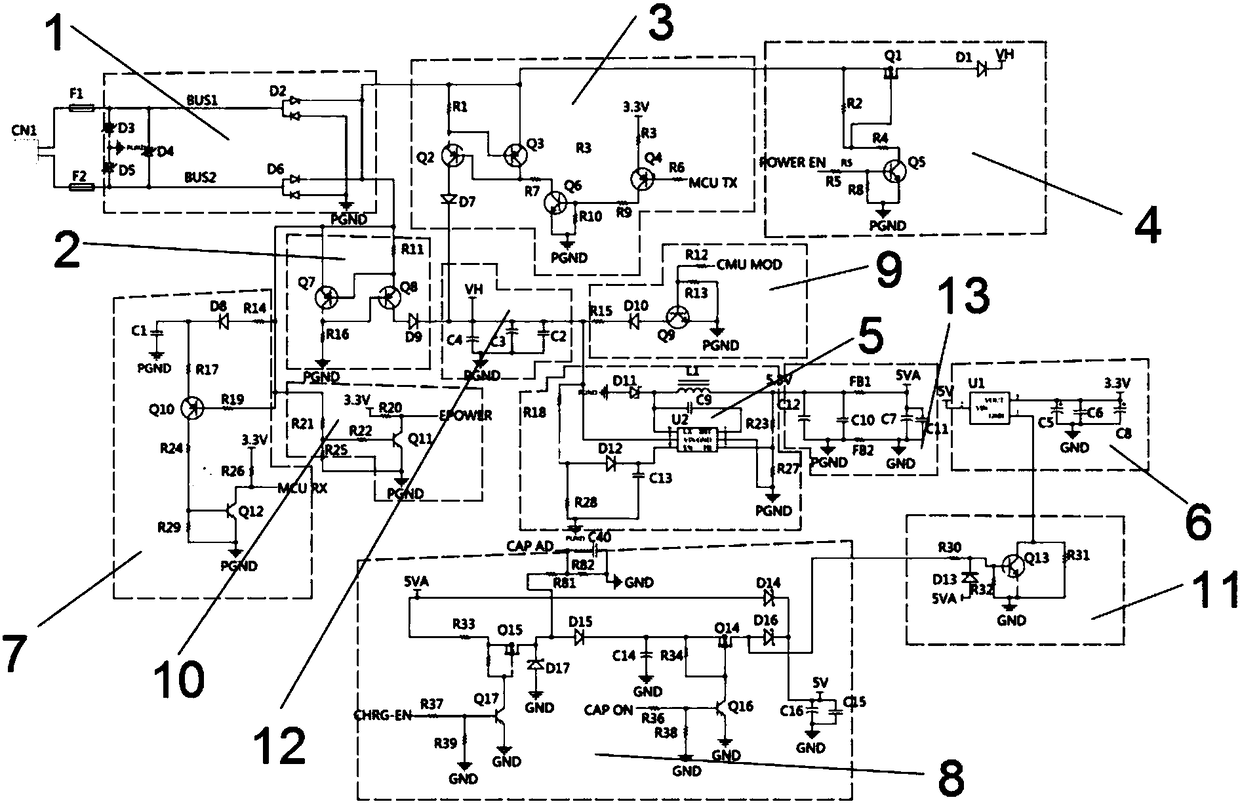
[0020] The MBUS control circuit for the temperature control valve of the present invention includes a single chip microcomputer, a rectifier circuit 1, a power supply circuit, an energy storage circuit 12, a DCDC step-down circuit 5, a filter circuit 13, a stable power supply chip circuit 6, a receiving circuit 7, a super Capacitance control circuit 8, reverse leakage protection circuit 11, energy storage circuit 12 and filter circuit 13, wherein the power supply circuit includes 6mA constant current source 2, 20mA controllable constant current source 3 and bus power supply control circuit 4 and constant current control Circuit 9.

[0021] Such as figure 1 Said, the rectifier circuit is connected to the MBUS bus through two power lines, wherein the 6mA constant current source 2 and the receiving circuit 7 are connected to the fuse F2 through ...


PUM


Abstract

The invention provides an MBUS control circuit for a temperature control valve. The MBUS control circuit for the temperature control valve comprises a single chip microcomputer for controlling the temperature control valve, a rectifying circuit in bus connection with MBUS, and a power supply circuit connected with the rectifying circuit and used for supplying power to the single chip microcomputer. The power supply circuit comprises a 6mA constant current source for providing a basic working current to the single chip microcomputer, a 20mA controllable constant current source for providing a large current to the single chip microcomputer and receiving a signal sent by the single chip microcomputer, and a constant-current control circuit for receiving a host signal; the 20mA controllable constant current source comprises a constant current source I1 and a control circuit for receiving the signal of the single chip microcomputer; and a receiving circuit for converting a high-low level sent by a host into a high-low level signal recognized by the single chip microcomputer is connected onto the rectifying circuit. According to the MBUS control circuit for the temperature control valveprovided by the invention, the adopted 20mA controllable constant current source receives a slave signal so as to accomplish data interaction with the host, and the adopted receiving circuit can convert the high-low level on the host into the signal recognized by a slave, so that the problems of power supply and communication between the host and the slave are solved through two power lines.

Description

technical field [0001] The invention belongs to the technical field of control circuits, and in particular relates to an MBUS control circuit for a temperature control valve and a control method thereof. Background technique [0002] MBUS is a bus protocol specially designed for remote data transmission of heat meters. It is an important technology for the digitization of data transmission of measuring instruments. It has been widely used in passive contacts such as water, electricity, gas, heat meters and other data collection occasions. . Because of its advantages of non-polarity and convenient construction, MBUS has been used more and more. For example, heating and water supply are widely used, but MBUS is only used for communication, and some enterprises use MBUS for power supply. For example, directly adding a DCDC step-down chip to the back end of the MBUS, the disadvantage of this solution is that when the load current increases, the bus current will fluctuate, causi...

Claims


Application Information

Patent Timeline
Patent Type & Authority Applications(China)
IPC IPC(8): F16K31/04F16K31/66
CPCF16K31/002F16K31/046
Inventor 陈红旗王兆杰王智陈家陪陈拥政
Owner RUINA INTELLIGENT EQUIP CO LTD
Learn More