Overcurrent protection circuit of switching voltage stabilizer

A technology of over-current protection circuit and switching voltage regulator, which is applied in the direction of emergency protection circuit devices and electrical components, etc. It can solve the problems of over-current protection clamp point rise, over-current protection, failure, etc., to achieve timeliness and effectiveness sex assurance effect

Inactive Publication Date: 2018-07-20
AMOLOGIC (SHANGHAI) CO LTD
View PDF2 Cites 0 Cited by
  • Summary
  • Abstract
  • Description
  • Claims
  • Application Information

AI Technical Summary

Problems solved by technology

[0003] However, traditional switching regulators controlled by PWM technology often use MOSFET (Metal-Oxide-Semiconductor Field-Effect Transistor, MOSFET for short) for overcurrent protection. As the working temperature rises gradually, the clamp point of the over-current protection increases, making timely and effective over-current protection impossible

Method used


Image

  • Overcurrent protection circuit of switching voltage stabilizer
  • Overcurrent protection circuit of switching voltage stabilizer
  • Overcurrent protection circuit of switching voltage stabilizer

Examples


Embodiment Construction

[0035] The following will clearly and completely describe the technical solutions in the embodiments of the present invention with reference to the accompanying drawings in the embodiments of the present invention. Obviously, the described embodiments are only some, not all, embodiments of the present invention. Based on the embodiments of the present invention, all other embodiments obtained by persons of ordinary skill in the art without creative efforts fall within the protection scope of the present invention.

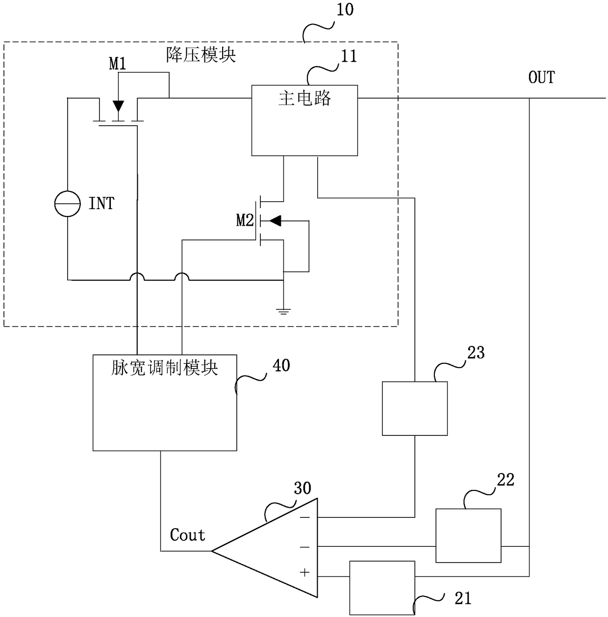
[0036] Such as figure 1 As shown, in a preferred embodiment, an overcurrent protection circuit for a switching regulator is proposed, which may include:

[0037] Step-down module 10, comprising:

[0038] A signal input terminal INT for receiving input signals and a signal output terminal OUT for outputting output signals;

[0039] The main circuit 11 is connected in series between the signal input terminal INT and the signal output terminal OUT;

[0040] A first...


PUM


Abstract

The invention relates to the field of power electronic technologies, and particularly relates to an overcurrent protection circuit of a switching voltage stabilizer. The overcurrent protection circuitcomprises a voltage reduction module, a first acquisition module, a second acquisition module, a third acquisition module, a comparison module and a pulse width modulation module, wherein the comparison module compares a superposition signal of a feedback signal and a ramp signal with an acquisition signal and outputs a comparison signal through a comparison output end; and a bipolar junction transistor with one end being grounded is connected between the first acquisition module and the comparison module. The clamping point of overcurrent protection can be kept at a low level even if the switching voltage stabilizer operates in a high-temperature environment, so that the timeliness and effectiveness of overcurrent protection can be guaranteed.

Description

technical field [0001] The invention relates to the technical field of power electronics, in particular to an overcurrent protection circuit of a switching regulator. Background technique [0002] With the rapid development of microelectronics technology, switching regulators are widely used in various occasions due to their advantages such as simple circuit structure, convenient adjustment, and high reliability. Switching regulators often use PWM (Pulse Width Modulation) control mode, which has Good noise reduction advantage. [0003] However, traditional switching regulators controlled by PWM technology often use MOSFET (Metal-Oxide-Semiconductor Field-Effect Transistor, MOSFET for short) for overcurrent protection. As the working temperature rises gradually, the clamping point of the over-current protection increases, making timely and effective over-current protection impossible. Contents of the invention [0004] In view of the above problems, the present invention ...

Claims


Application Information

Patent Timeline
IPC IPC(8): H02H7/12
CPCH02H7/1213
Inventor 樊茂
Owner AMOLOGIC (SHANGHAI) CO LTD
Why Eureka
Try Eureka