Greenhouse turning-free reciprocating ridger
A technology for ridging machines and driving motors, which is applied to agricultural machinery and implements, shovels, plows, etc. It can solve the problems of high labor consumption, small turning space in greenhouses, and low uniformity of manual ridging, so as to improve uniformity and smoothness performance, improve stability, enhance the effect of connection strength
- Summary
- Abstract
- Description
- Claims
- Application Information
AI Technical Summary
Problems solved by technology
Method used
Image


Examples
Embodiment 1
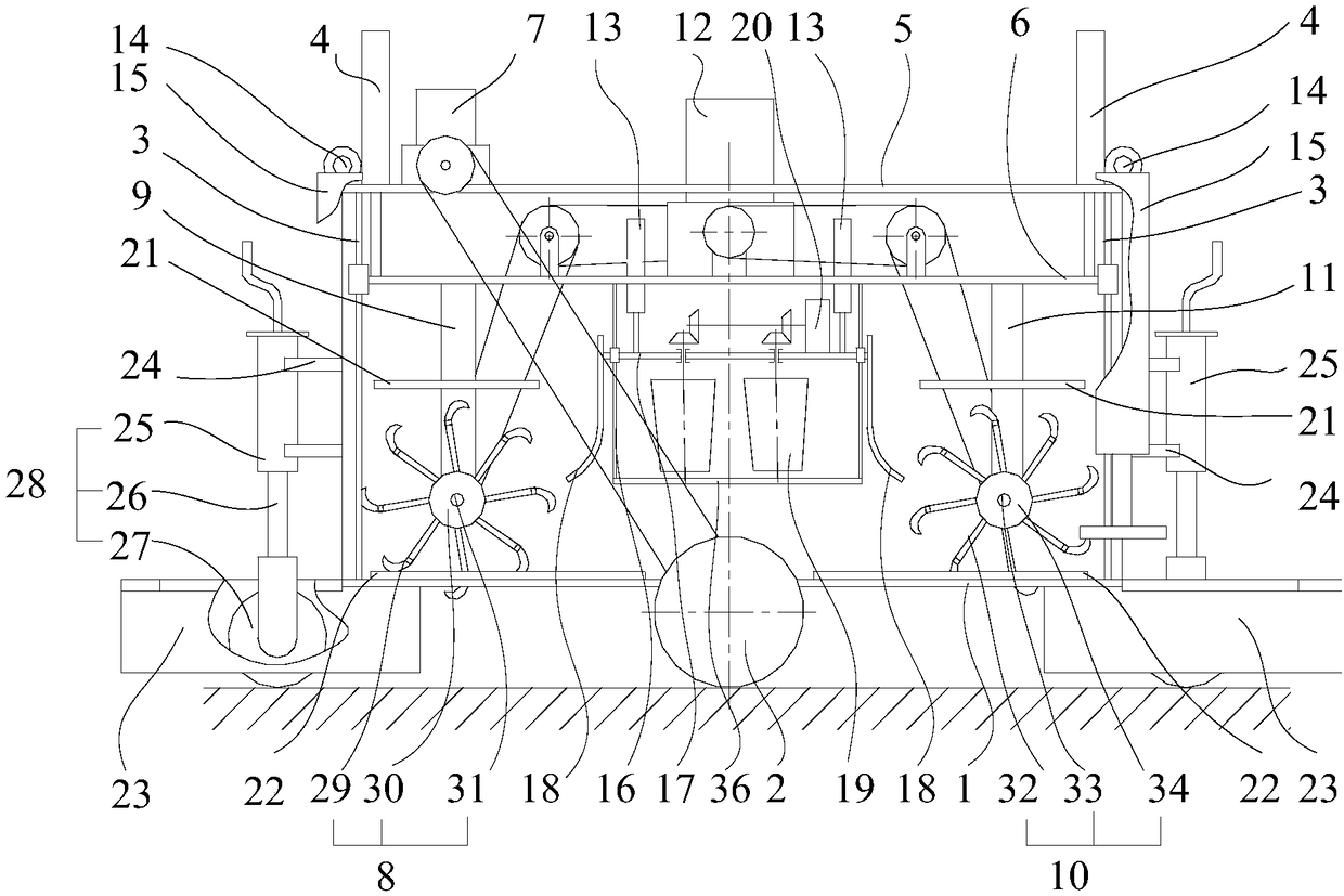
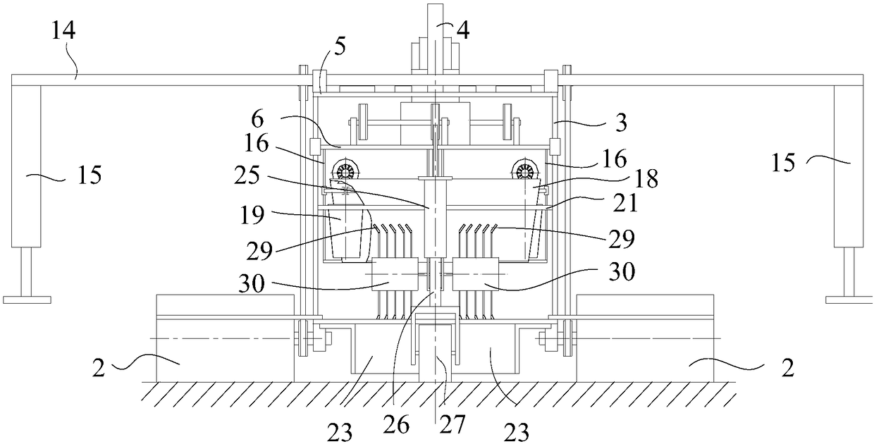
[0035] Such as Figure 1 to Figure 4 A greenhouse-free reciprocating ridging machine shown in this embodiment includes: a first lower frame 1, the first lower frame 1 is a rectangular frame and placed horizontally, and the middle parts of the two long sides of the rectangular frame are respectively rotated and connected with One road wheel 2, the axis of the road wheel 2 is perpendicular to the long side of the rectangular frame, the axes of the two road wheels 2 are coaxial; multiple first slide rails 3, the same end of the multiple first slide rails 3 and the first lower layer The upper surface of the frame 1 is fixedly connected, the other end is fixedly connected with an upper board 5, the upper board 5 is arranged in parallel with the first lower frame 1, the upper board 5 is fixedly connected with two first electric push rods 4, the upper surface of the upper board 5 The first drive motor 7 is fixedly connected, and the first drive motor 7 is connected to the two road wh...
Embodiment 2
[0051] Such as Figure 1 to Figure 4 A greenhouse-free reciprocating ridging machine shown in this embodiment includes: a first lower frame 1, the first lower frame 1 is a rectangular frame and placed horizontally, and the middle parts of the two long sides of the rectangular frame are respectively rotated and connected with One road wheel 2, the axis of the road wheel 2 is perpendicular to the long side of the rectangular frame, the axes of the two road wheels 2 are coaxial; four first slide rails 3, the four first slide rails 3 have one end and the first lower layer The upper surface of the frame 1 is fixedly connected, the other end is fixedly connected with an upper board 5, the upper board 5 is arranged in parallel with the first lower frame 1, the upper board 5 is fixedly connected with two first electric push rods 4, the upper surface of the upper board 5 The first drive motor 7 is fixedly connected, and the first drive motor 7 is connected to the two traveling wheels 2...
Embodiment 3
[0061] A kind of reciprocating ridging machine without turning head in the greenhouse in this embodiment includes such as Figure 1 to Figure 4 All the technical features of the U-turn-free reciprocating ridging machine shown in the greenhouse, in addition to two road wheel height adjustment devices and two road wheel drive tensioning devices, one end of each road wheel height adjustment device and two ends of the road wheel The bearing seat at the top is fixedly connected, and the other end is fixedly connected with the first lower frame 1. Each road wheel transmission tensioning device is used to tension the chain driving the road wheel to rotate. Preferably, the road wheel height adjustment device includes Screw, guide post, adjustment plate and two adjustment nuts, one end of the screw rod and guide post is fixed on the first lower frame 1, the screw rod and guide post are arranged in parallel and pass through the adjustment plate, and the adjustment plate is fixed on the r...
PUM
 Abstract
Description
Claims
Application Information
 - R&D
- Intellectual Property
- Life Sciences
- Materials
- Tech Scout
- Unparalleled Data Quality
- Higher Quality Content
- 60% Fewer Hallucinations
Browse by: Latest US Patents, China's latest patents, Technical Efficacy Thesaurus, Application Domain, Technology Topic, Popular Technical Reports.
© 2025 PatSnap. All rights reserved.Legal|Privacy policy|Modern Slavery Act Transparency Statement|Sitemap|About US| Contact US: help@patsnap.com