Metal separation device for construction waste

A technology for metal separation and construction waste, applied in the direction of solid separation, magnetic separation, separation methods, etc., can solve the problems of the reduction of the working efficiency of the crusher, and achieve the effect of improving the working efficiency

Active Publication Date: 2018-07-24
徐州汉兴再生资源有限公司
View PDF4 Cites 20 Cited by
  • Summary
  • Abstract
  • Description
  • Claims
  • Application Information

AI Technical Summary

Problems solved by technology

[0006] The purpose of the present invention is to provide a construction waste metal separation device to solve the problem in the prior art that during the crushing process of the crusher, the separated metal needs to be shut down to discharge the crusher, which reduces the working efficiency of the crusher.

Method used


Image

  • Metal separation device for construction waste
  • Metal separation device for construction waste
  • Metal separation device for construction waste

Examples


Embodiment 1

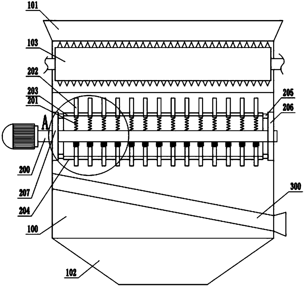
[0031] Such as figure 1 Shown is embodiment one of the present invention, has announced construction waste metal separating device, comprises the crushing box casing 100 that is fixed on the frame, and the upper end of casing 100 is provided with the feeding hopper 101 that dumps construction waste, and casing 100 The lower end of the tank is provided with a discharge hopper 102 for the discharge of crushed and separated construction waste. A pair of motor-driven first crushing rollers 103 and second crushing rollers 104 are provided in the box body 100 near the bottom of the feed hopper 101. The two crushing rollers The surface of the crusher is equipped with conical teeth for crushing construction waste, and the two crushing rollers rotate in opposite directions and mesh with each other.

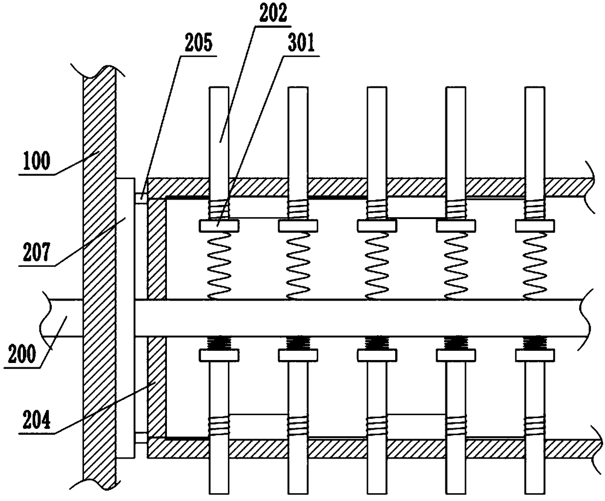
[0032]Just below the first crushing roller 103 is provided with a support shaft 200 driven by a motor. The support shaft 200 in the present invention is a permanent magnet. The installatio...

Embodiment 2

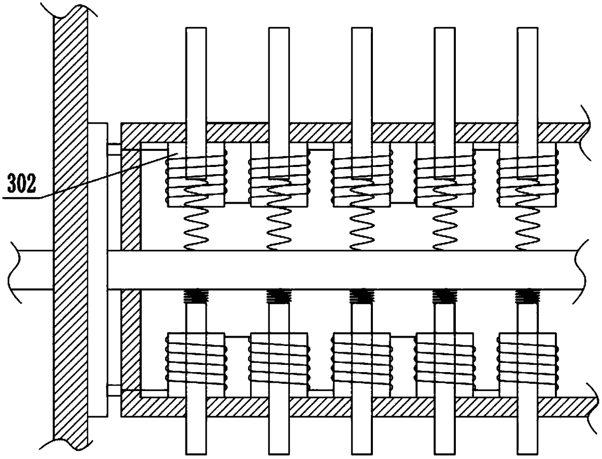
[0038] Such as image 3 Shown is Embodiment 2 of the present invention, and the difference from Embodiment 1 is: a sleeve 302 fixed on the inner wall of the rotating shaft 204 is provided outside the iron core 202, and the coil is wound on the outer wall of the sleeve 302; Figure 4 As shown, a thread groove 303 is provided on the outer wall of the iron core 202 , and a slider 304 slidably connected to the thread groove 303 is fixed on the inner wall of the sleeve 302 .

[0039] During the specific implementation, the difference from the implementation process of the first embodiment is that: when the coil is energized and de-energized, the iron core 202 moves in a spiral trajectory in the connection hole.

Embodiment 3

[0041] Such as Figure 5 Shown is Embodiment 3 of the present invention, and the difference from Embodiment 1 and Embodiment 2 is that in order to reduce the dust flying after the construction waste is crushed, an air suction port 305 is provided on the side wall of the box 100 below the second crushing roller 104 , the air suction port 305 is connected to a dust removal device 307 through a pipeline 306 , the dust removal device 307 includes an air pump and a filter bag, and the filter bag is connected to a water tank 308 through a pipeline 306 .

[0042] During concrete implementation, before this device carries out crushing and crushing construction waste, fill water in water tank 308, make pipeline 306 extend into water, start the suction pump in the dust removal device 307 afterward, the dust that produces in the crushing process and support shaft 200 rotate The dust brought up by the agitation enters the pipeline 306 from the air suction port 305 by the adsorption force ...


PUM


Abstract

The invention belongs to the technical field of construction equipment, and specifically discloses a metal separation device for construction waste. A feed hopper is arranged at the upper end of a box; engaged crushing rollers are mounted below the feed hopper; a discharge hopper is arranged at the lower end of the box; a supporting shaft is arranged below the crushing rollers; a ferromagnetic unit comprises a spring; the upper end of the spring is connected with an iron core; a coil is wound on the periphery of the iron core; a single electromagnet group comprises a plurality of ferromagneticunits; the ferromagnetic units are arranged in a row in the axial direction; a rotating shaft is coaxially fixed outside the supporting shaft; a plurality of connecting holes are formed in the rotating shaft; coils in the single electromagnet group are connected into a wire; two ends of the wire are connected with conducting plates respectively; a negative electrode plate and a positive electrodeplate in frictional connection with the conducting plates are arranged on the inner wall of the box at two ends of the rotating shaft; a screen is arranged below the rotating shaft slantly; and a slag outlet is formed in the side wall of the box at the lower end of the screen. The metal waste inside the construction waste can be separated continuously by adopting the technical scheme, and machinehalt is not needed.

Description

technical field [0001] The invention relates to the technical field of construction equipment, in particular to a metal separation device for construction waste. Background technique [0002] Construction waste refers to the waste generated during the construction, laying or demolition, and repair of various buildings, structures, and pipe networks by construction units or individuals. Usually, construction waste is shredded, which is not only convenient for transportation, but also Moreover, some construction waste contains a large amount of ferromagnetic metal waste, and the metal waste in the crushed construction waste can be classified and recycled. However, the existing classification method mainly relies on manual sorting, which is inefficient and has a great Increased labor intensity of workers. [0003] In order to solve the above problems, the Chinese invention patent with the patent publication number: CN106925378A has announced a kind of construction waste crushe...

Claims


Application Information

Patent Timeline
Patent Type & Authority Applications(China)
IPC IPC(8): B02C4/08B02C23/14B03C1/12B08B15/04B01D47/02
CPCB01D47/02B02C4/08B02C23/14B02C2201/06B03C1/12B08B15/04
Inventor 张谦
Owner 徐州汉兴再生资源有限公司
Why Eureka
Try Eureka