Die casting cooling mechanism

A technology of cooling mechanism and die-casting parts, which is applied in the field of cooling equipment, can solve problems such as damage to die-casting parts and too long cooling time of separate air cooling, and achieve the effects of improving cooling efficiency, saving factory space, and saving land costs

Inactive Publication Date: 2018-07-24
成都恒西亚机械工业有限责任公司
View PDF0 Cites 3 Cited by
  • Summary
  • Abstract
  • Description
  • Claims
  • Application Information

AI Technical Summary

Problems solved by technology

[0003] The technical problem to be solved by the present invention is that direct water cooling may cause damage to die castings, and the cooling time of air cooling alone is too long

Method used


Image

  • Die casting cooling mechanism
  • Die casting cooling mechanism
  • Die casting cooling mechanism

Examples


Embodiment Construction

[0018] In order to have a clearer understanding of the technical features, purposes and effects of the present invention, the specific implementation manners of the present invention will now be described with reference to the accompanying drawings.

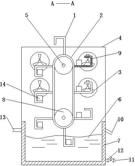
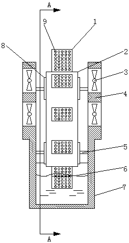
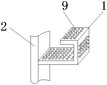
[0019] like Figure 1~3 As shown, the present invention includes a cooling plate 1, a conveyor belt 2, a conveyor roller 8, a fan 3 and a water tank 7; Clothed on the outer surface of the conveyor belt 2, the cooling plate 1 is provided with ventilation holes 9, the ventilation holes 9 are evenly arranged on the three plates of the cooling plate 1, the conveyor belt 2 is a metal mesh conveyor belt, and is arranged on two conveyor rollers 8 , the transmission roller 8 is arranged on the transmission shaft 5 at the center of the transmission roller 5, and the two ends of the transmission shaft 5 are arranged in the fan box 4, and the fan box 4 is arranged symmetrically before and after the conveyor belt 2, and the fan box 4 is also...


PUM


Abstract

The invention discloses a die casting cooling mechanism. The die casting cooling mechanism comprises a cooling plate, a conveyor belt, a conveying roller, fans and a water tank, wherein a J-shaped cooling plate is arranged on the conveyor belt, a die casting is put in from the cooling plate on the right side, a fan is arranged in front of and behind the conveyor belt respectively, and the water tank is arranged at the lower part of the conveyor belt. The die casting cooling mechanism provided by the invention has a vertical structure, saves factory spaces, is more compact in structure and saves the land cost, and die castings are subjected to air cooling at first, and then water cooling, are cooled more uniformly and fully, and then are further subjected to air cooling while drying the moisture on the die castings.

Description

technical field [0001] The invention relates to the field of cooling equipment, in particular to a die casting cooling mechanism. Background technique [0002] At present, the cooling methods of die-casting parts are: natural cooling, water cooling and air cooling. For die-casting aluminum or die-casting zinc, direct immersion or water spray cooling will cause a lot of internal stress inside the die-casting parts, and even cracks. If air cooling is used, it will It requires a long cooling time, which not only takes up a lot of space for heat dissipation, but also has low cooling efficiency and prolongs the construction period. Therefore, how to overcome the above technical problems has become a technical problem to be solved urgently by those skilled in the art. Contents of the invention [0003] The technical problem to be solved by the present invention is that direct water cooling may cause damage to die castings, and the cooling time of air cooling alone is too long. ...

Claims


Application Information

Patent Timeline
Patent Type & Authority Applications(China)
IPC IPC(8): B22D17/20B22D30/00
CPCB22D17/20B22D30/00
Inventor 蒲琨阳
Owner 成都恒西亚机械工业有限责任公司
Why Eureka
Try Eureka