
cutting equipment

A technology for cutting equipment and iron filings, which is applied in the direction of metal processing equipment, maintenance and safety accessories, metal processing machinery parts, etc. It can solve the problems of large space occupation, large amount of steel cutting, and high operation difficulty, so as to reduce the workload and improve The effect of cutting efficiency, flexible cutting operation

Active Publication Date: 2020-11-13
HUIZHOU UNIV
View PDF14 Cites 0 Cited by
  • Summary
  • Abstract
  • Description
  • Claims
  • Application Information

AI Technical Summary

Problems solved by technology

[0003] However, in the process of mechanical processing and production, the cutting volume of steel is very large, and the efficiency of manual cutting cannot keep up with the progress of processing and production. Although some special cutting equipment can improve the cutting efficiency, its cost is high and it takes up more space. Large and difficult to operate

Method used


Image

  • cutting equipment
  • cutting equipment

Examples


Embodiment Construction

[0023] In order to facilitate understanding of the present invention, the present invention will be further described with reference to the related drawings. The preferred embodiment of the present invention is given in the drawings. However, the present invention can be implemented in many different forms, and is not limited to the embodiments described herein. Conversely, the purpose of providing these embodiments is to make the disclosure of the present invention more thoroughly comprehensively.

[0024] It should be noted that when the element is referred to as "fixed to" another element, it can be directly in another element or may exist in the hidden element. When an element is considered to be "connected" another element, it can be directly connected to another element or may exist at the same time. The term "vertical", "horizontal", "horizontal", "left", "right", and similar expressions are merely illustrative, and the only embodiment is not shown.

[0025] All technical a...


PUM


Abstract

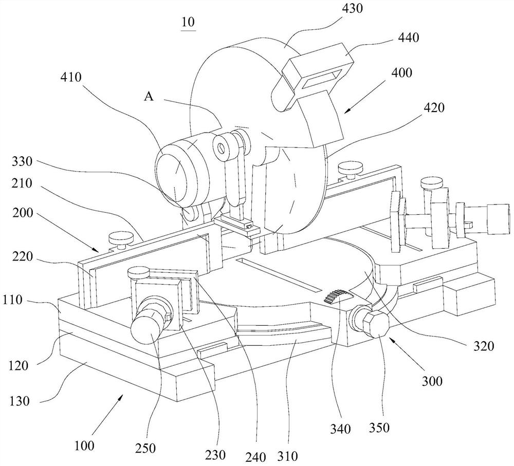
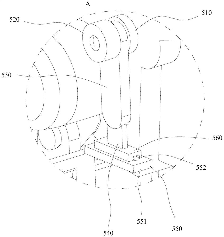
Cutting equipment comprises a feeding positioning seat, automatic feeding assemblies, an angle adjusting disk and a cutting assembly. The feeding positioning seat comprises a bearing plate, a reinforcing plate and a supporting foot seat, the bearing plate is mounted on the reinforcing plate, and the supporting foot seat is mounted on the reinforcing plate. The automatic feeding assemblies compriselimiting plates, feeding tracks, feeding drivers, positioning mounting blocks, positioning base plates and telescopic electric cylinders. The angle adjusting disk comprises an end face gear plate, arotary table, a connecting seat, an adjusting gear and an angle adjusting motor. The cutting assembly comprises a cutting motor, a swing driving motor, a cutting blade, a cutting protective shell andan armrest. The cutting equipment is provided with the feeding positioning seat, the automatic feeding assemblies, the angle adjusting disk and the cutting assembly, and the feeding positioning seat is matched with the automatic feeding assemblies to position steel to be cut, so that the cut-off size can be precisely controlled, the cutting operation can be flexibly performed, and the cutting efficiency of the steel is improved.

Description

Technical field [0001] The present invention relates to a steel cutting technology, and particularly relates to a cutting apparatus. Background technique [0002] With the development of modern machinery industry, cutting quality, continuously improve the accuracy requirements, to improve production efficiency, reduce production costs, have requirements for automatic cutting function of high intelligence is also improved. In the machining process, sheet metal cutting in the usual manner with a hand-cut, semi-automatic cutting machine and a CNC cutting machine. Flexible hand-cut, hand-cut but poor quality, large dimensional error, waste of material, the subsequent processing workload, and poor working conditions, low production efficiency. Semi-automatic cutting machine profile cutting machine, better quality of cutting a workpiece, using a cutting die because not suitable for single-piece, small and large workpiece cutting. Although other types of semi-automatic cutting machine t...

Claims


Application Information

Patent Timeline
Patent Type & Authority Patents(China)
IPC IPC(8): B23Q7/00B23Q1/25B23Q11/00
CPCB23Q1/25B23Q7/00B23Q11/0042B23Q11/0064
Inventor 王健海陈淑环张璇
Owner HUIZHOU UNIV
Learn More