
Optical free curved surface polishing device and method

A free and curved surface technology, applied in the direction of optical surface grinder, grinding automatic control device, grinding/polishing equipment, etc., can solve the problems of difficult polishing process and difficult surface, and achieve the effect of small size and convenient movement

Pending Publication Date: 2018-07-24
DALIAN UNIV OF TECH
View PDF11 Cites 5 Cited by
  • Summary
  • Abstract
  • Description
  • Claims
  • Application Information

AI Technical Summary

Problems solved by technology

However, as the size of optical devices becomes smaller and smaller, especially the concave surface shape, the polishing process becomes more and more difficult, making the polishing of tiny optical free-form surfaces one of the urgent issues to be solved in the field of material processing
At present, although the magnetorheological polishing method has been used to polish free-form surfaces, it is still difficult for surfaces with small sizes and complex shapes.

Method used


Image

  • Optical free curved surface polishing device and method
  • Optical free curved surface polishing device and method
  • Optical free curved surface polishing device and method

Examples


Embodiment Construction

[0031] The present invention will be further described below in conjunction with the accompanying drawings.

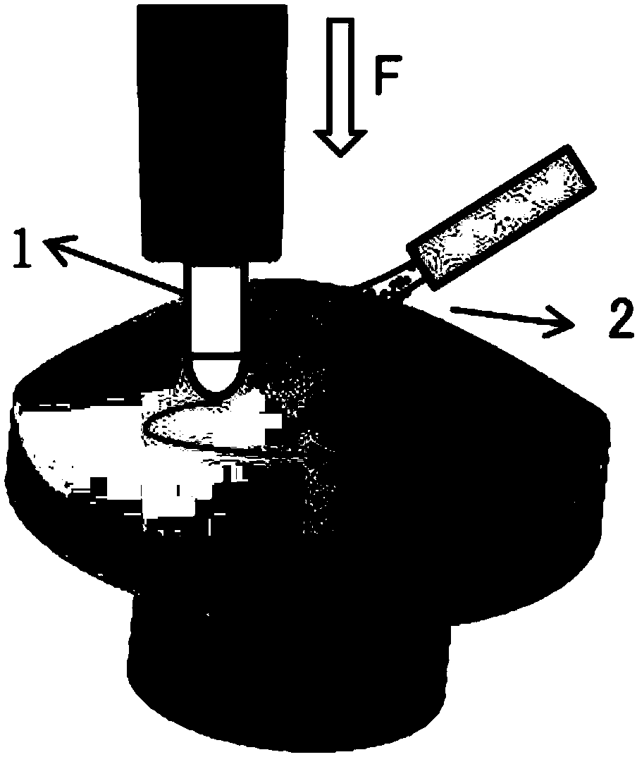
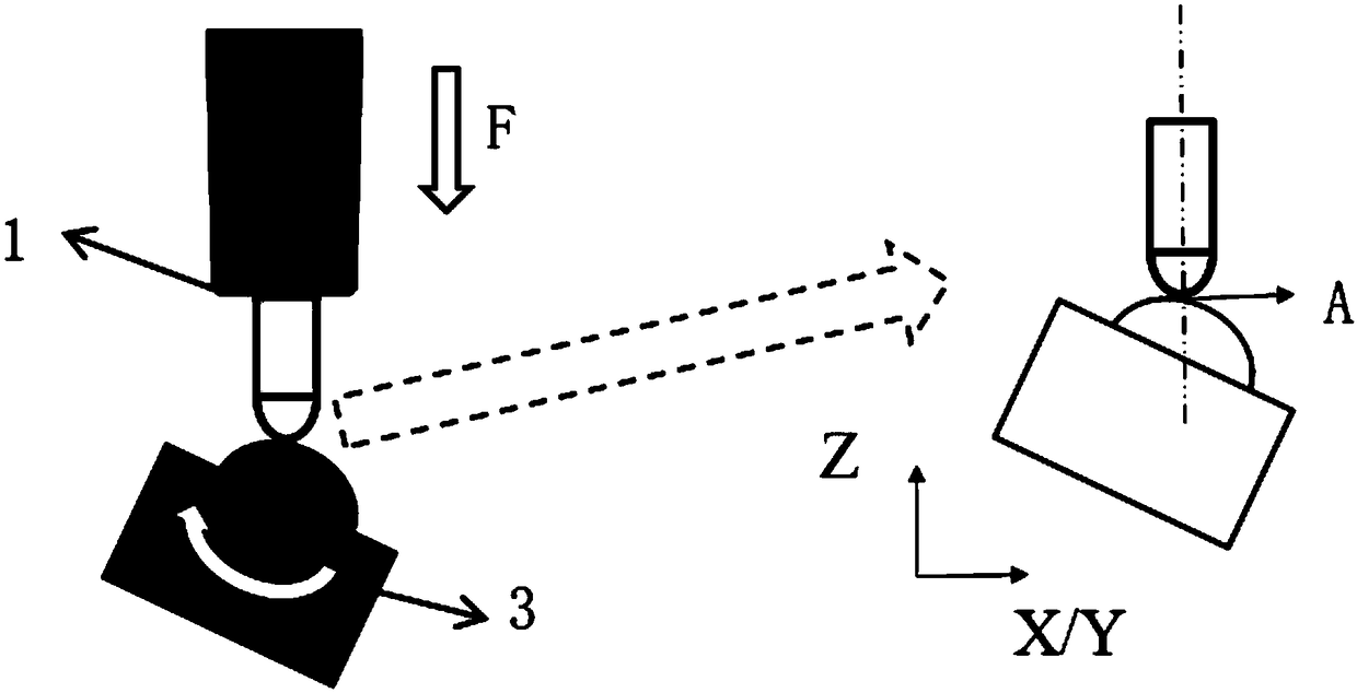
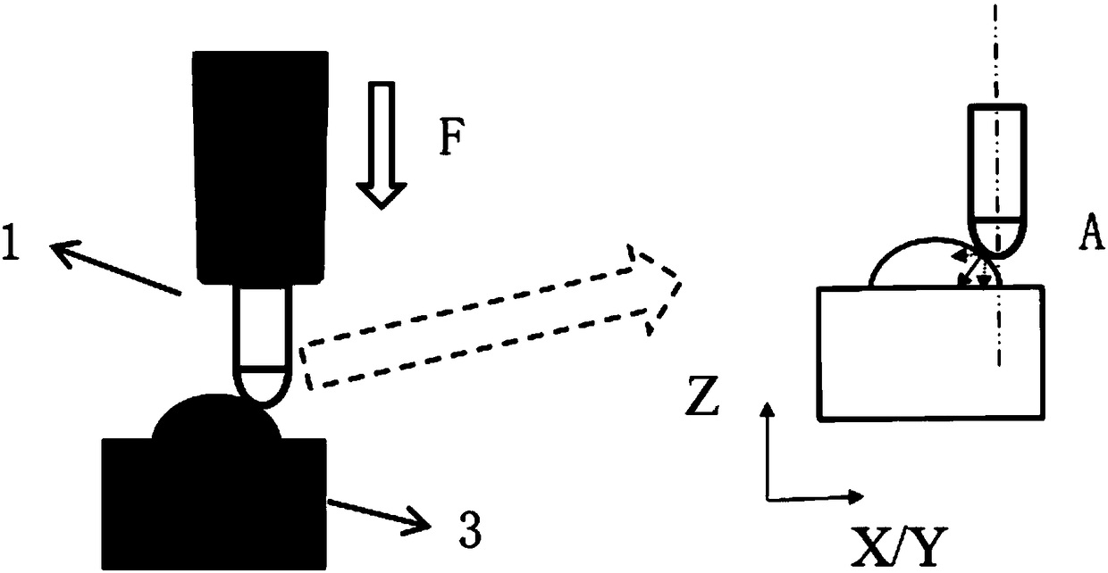
[0032] A vibration polishing device for a micro optical free-form surface, the vibration polishing device comprises a vibration polishing head 1, a micro optical free-form surface 3, a control system 5, a PC 6, a five-axis numerical control platform 7, and a polishing pressure control mechanism 8.

[0033] The control system 5 is located above the movable worktable 4 and includes a driver, a numerical control system, and a controller; the driver is connected to the vibration polishing head 1 , the numerical control system is connected to the five-axis numerical control platform 7 for communication, and the controller is connected to the polishing pressure control mechanism 8 . The PC 6 is located above the movable workbench 4 and is connected to the control system 5. After setting the polishing parameters, the PC 6 transmits them to the control system 5, and then drives...


PUM


Abstract

The invention discloses an optical free curved surface polishing device and method, and belongs to the field of optical manufacturing. A vibration polishing device comprises a vibration polishing head, a control system, a PC computer, a five-axis numerical control platform and a polishing pressure control mechanism. The control system and the PC computer are respectively positioned above and belowa movable worktable; a driver in the control system is connected with the vibration polishing head; a numerical control system communicates with the five-axis numerical control platform; a controlleris connected with the polishing pressure control mechanism; the PC computer is connected with the control system, and sets polishing parameters for transmission to the control system to control the whole polishing device; and a micro displacement driving device in the polishing pressure control mechanism is connected with the polishing head. A vibration auxiliary polishing mode is adopted; aimingat continuous surfaces, such as axial symmetry and off-axis non-spherical surfaces, real-time precise control of a polishing head vibration mode, a polishing trajectory and a polishing pressure can be realized at the same time, and the submicron surface figure accuracy and the subnanometer surface roughness can be achieved; and the polishing device has the advantages of system integration, smallsize, convenience to move and the like.

Description

technical field [0001] The invention belongs to the field of optical manufacturing, and relates to a polishing device and method for an optical free-form surface. Background technique [0002] Optical free-form surface is a special type of free-form surface. Due to its new optical design concept, it can maximize the performance of the optical system, such as correcting aberrations, improving image quality, and expanding the field of view. At the same time, it can optimize the optical system, such as reducing Weight, size reduction, cost reduction, etc. are the core key components of the new generation of optical systems (Fang FZ, Zhang XD, Weckenmann A, Zhang GX, Evans C. Manufacturing and measurement of freeformoptics. CIRP Annals 2013; 62:823-846. ). [0003] One method for the manufacture of optical free-form surfaces is direct processing, and one method is to replicate through molds. The method of duplicating through the mold can obtain higher efficiency and product st...

Claims


Application Information

Patent Timeline
IPC IPC(8): B24B1/00B24B13/00B24B51/00
CPCB24B1/00B24B13/00B24B51/00Y02P70/10
Inventor 郭江康仁科郭东明
Owner DALIAN UNIV OF TECH
Learn More